CCNA 200-301 Study (1)

CCNA Volume 1
Introduction to TCP/IP
Network Protocol
| Protocol Characteristic | Description |
| Message format | When a message is sent, it must use a specific format or structure. Message formats depend on the type of message and the channel that is used to deliver the message. |
| Message size | The rules that govern the size of the pieces communicated across the network are very strict. They can also be different, depending on the channel used. When a long message is sent from one host to another over a network, it may be necessary to break the message into smaller pieces in order to ensure that the message can be delivered reliably. |
| Timing | Many network communication functions are dependent on timing. Timing determines the speed at which the bits are transmitted across the network. It also affects when an individual host can send data and the total amount of data that can be sent in any one transmission. |
| Encapsulation | Each message transmitted on a network must include a header that contains addressing information that identifies the source and destination hosts, otherwise it cannot be delivered. Encapsulation is the process of adding this information to the pieces of data that make up the message. In addition to addressing, there may be other information in the header that ensures that the message is delivered to the correct application on the destination host. |
| Message pattern | Some messages require an acknowledgment before the next message can be sent. This type of request/response pattern is a common aspect of many networking protocols. However, there are other types of messages that may be simply streamed across the network, without concern as to whether they reach their destination. |
Common Methods of Data Transmission
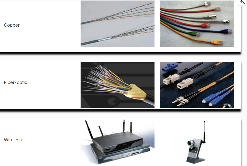
- Electrical signal transmission is achieved by representing data as electrical pulses on copper wire.
- Optical signals: transmission is achieved by converting the electrical signals into light pulses.
- Wireless signal transmission is achieved by using infrared, microwave, or radio waves through the air.
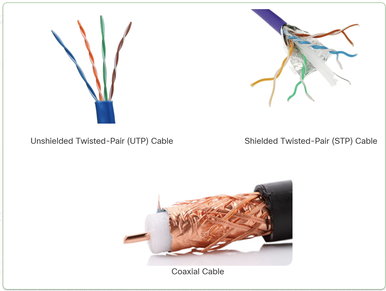
- UTP (Unshielded Twisted Pair): No shielding, cheaper, more flexible, but less resistant to interference. Used in home and office networks.
- STP (Shielded Twisted Pair): Has shielding to reduce interference, but is more expensive and less flexible. Used in industrial or high-EMI environments.
Types of Fiber Optic Cables
- Single-Mode Fiber (SMF)
- Uses a single beam of light (laser).
- Supports long distances (up to 100+ km).
- Higher bandwidth but more expensive.
- Multi-Mode Fiber (MMF)
- Uses multiple beams of light (LED).
- Supports shorter distances (up to 2 km).
- Cheaper but has more signal loss due to modal dispersion
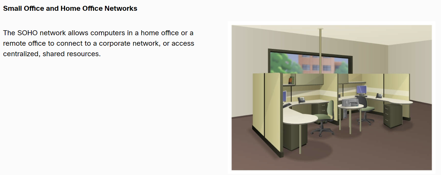
Network Documentation
Network documentation is essential for managing, troubleshooting, and securing a network.
Physical Documentation
Focuses on hardware and cabling layout.
🔹 Includes:
✔ Network topology diagrams (physical)
✔ Rack elevation and cabling layout
✔ Hardware inventory (routers, switches, firewalls)
✔ Power & cooling systems
✅ Used for troubleshooting hardware, expansion planning, and audits.
📌 Logical Documentation
Focuses on data flow and network configurations.
🔹 Includes:
✔ Logical network topology diagrams
✔ IP addressing, VLANs, and routing tables
✔ Security policies and firewall rules
✔ Performance and monitoring reports
✅ Helps in troubleshooting, security management, and network planning.
Bandwidth Vs Throughput
Bandwidth is the capacity of a medium to carry data. Digital bandwidth measures the amount of data that can flow from one place to another in a given amount of time. Bandwidth is typically measured in the number of bits that (theoretically) can be sent across the media in a second. Common bandwidth measurements are as follows:
Thousands of bits per second (Kbps)
Millions of bits per second (Mbps)
Billions of bits per second (Gbps)
Like bandwidth, throughput measures the transfer of bits across the media over a given period. However, due to several factors, throughput does not usually match the specified bandwidth. Many factors influence throughput, including:
- The amount of data being sent and received over the connection.
- The types of data being transmitted.
- The latency is created by the number of network devices encountered between the source and the destination.
Latency refers to the amount of time, including delays, for data to travel from one given point to another.
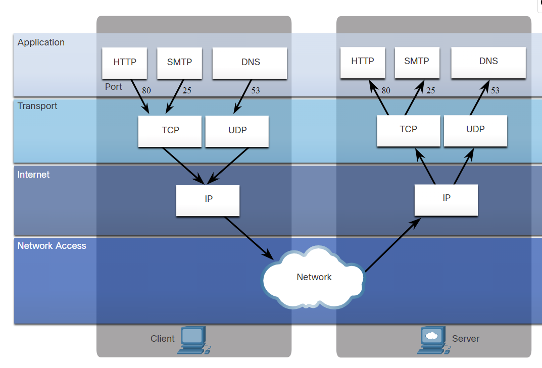
TCP (Transmission Control Protocol) is a standard protocol that defines how to establish and maintain a network connection through which an application program can exchange data.
The TCP/IP model both defines and references a large collection of protocols that allow computers to communicate.
The name TCP/IP is simply the name of the two most common protocols (TCP and IP) separated by, which means the model refers to the most preferred protocols.
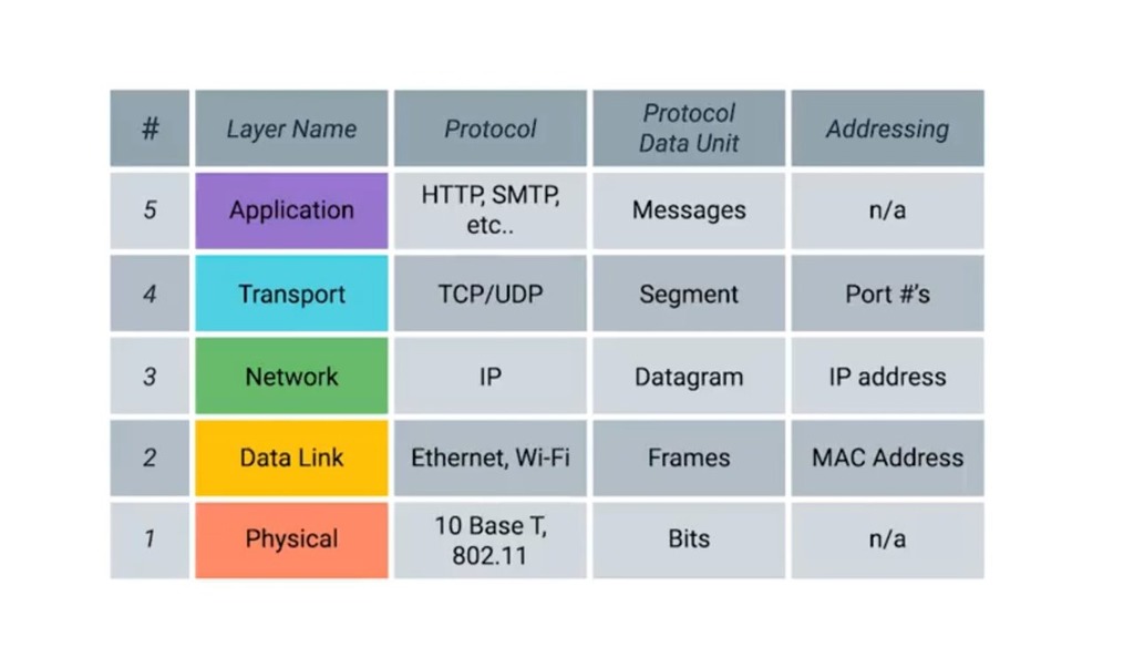
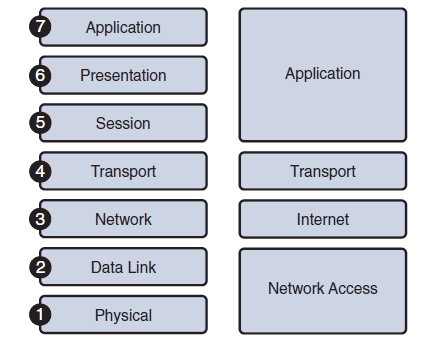
Application Layer: Refers to interfaces between the network and application software. It also includes authentication services.
Note: The application layer does not define the application itself.
Transport Layer: Provides a variety of services between two host computers, including connection establishment and termination, flow control, error recovery, and segmentation of large data blocks into smaller parts for transmission. the two most commonly used transport layer protocols are the Transmission control protocol (TCP) and the user datagram protocol (UDP).
Network: Refers to logical addressing, routing, and path determination.
Data Link: Formats data into frames appropriate for transmission onto some physical medium. Defines rules for when the medium can be used. Defines the means by which to recognize transmission errors.
Physical: Defines the electrical, optical, cabling, connectors, and procedural details required for transmitting bits, represented as some form of energy passing over a physical medium.
| TCP | UDP | |
| Full form | It stands for Transmission Control Protocol. | It stands for User Datagram Protocol. |
| Type of connection | It is a connection-oriented protocol, which means that the connection needs to be established before the data is transmitted over the network. | It is a connectionless protocol, which means that it sends the data without checking whether the system is ready to receive or not. |
| Reliable | reliable protocol as it provides assurance for the delivery of data packets. | unreliable protocol as it does not take a guarantee for the delivery of packets. |
| Speed | slower than UDP as it performs error checking, flow control, and provides assurance for the delivery of data. | faster than TCP as it does not guarantee the delivery of data packets. |
| Header size | The size of TCP is 20 bytes. | The size of the UDP is 8 bytes. |
| Acknowledgment | TCP uses the three-way handshake concept. In this concept, if the sender receives the ACK, then the sender will send the data. TCP also has the ability to resend the lost data. | UDP does not wait for any acknowledgment; it just sends the data. |
| Flow control mechanism | It follows the flow control mechanism in which too many packets cannot be sent to the receiver at the same time. | This protocol follows no such mechanism. |
| Error checking | TCP performs error checking by using a checksum. When the data is corrected, then the data is retransmitted to the receiver. | It does not perform any error checking, and also does not resend the lost data packets. |
| Applications | This protocol is mainly used where a secure and reliable communication process is required, like military services, web browsing, and e-mail. | This protocol is used where fast communication is required and does not care about reliability like VoIP, game streaming, video and music streaming, etc. |
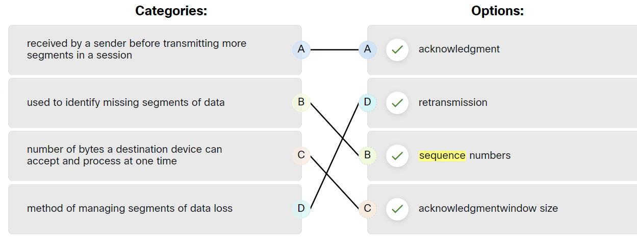
Which two TCP header fields are used to confirm receipt of data?
- Sequence Number
- Acknowledge number
How does TCP communicate?
- Three-way handshake.
- SYN, ACK, FIN, RST.
- Windows size (65,535)
The six control bits flags are as follows:
- SYN: It is used to establish a connection between the hosts.
- ACK: Acknowledgment flag used in connection establishment and session termination. If the ACK is set to 0, then it means that the data packet does not contain an acknowledgement.
- PSH: is a control flag used to indicate that the receiving device should deliver the data to the receiving application as soon as possible, rather than buffering it.
- RST: Reset the connection when an error or timeout occurs.
- URG: It represents an urgent pointer. If it is set, then the data is processed urgently.
- FIN: No more data from sender and used in session termination
When the PSH flag is set, it instructs the receiving device to deliver the data immediately to the application layer without waiting for more data to arrive.
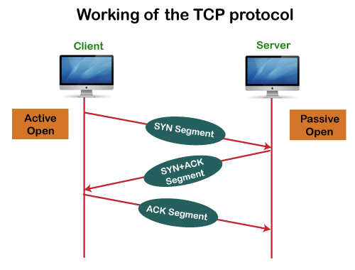
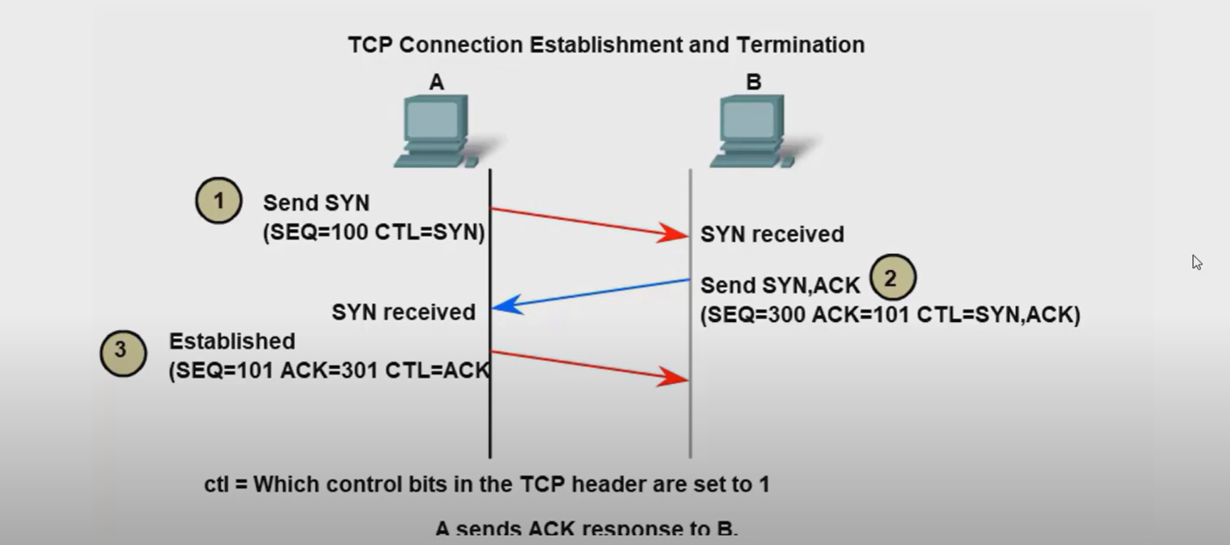
Establish TCP Connection:

Terminate TCP connection:
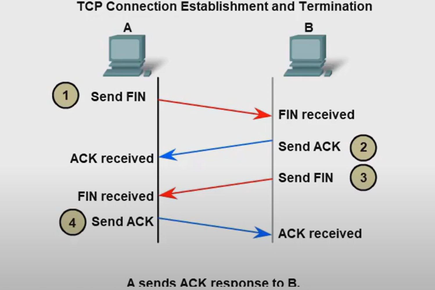
How many exchanges are needed to end both sessions between two hosts?
Four exchanges.
TCP Reliability - Data Loss and Retransmission
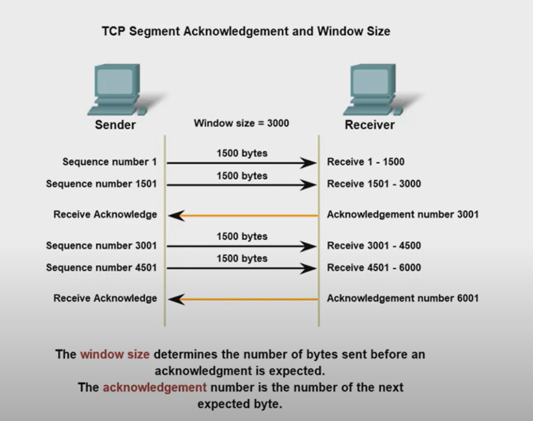
The Sequence (SEQ) number and Acknowledge (ACK) number are used together to confirm receipt of the bytes of data contained in the transmitted segments.
- What field is used by the destination host to reassemble segments into the original order? Sequence Number
What field is used to provide flow control? Window Size
Flow control is the amount of data that the destination can receive and process reliably.
- Which field in the TCP header indicates the status of the three-way handshake process? control bits
- Network congestion has resulted in the source learning of the loss of TCP segments that were sent to the destination. What is one way that the TCP protocol addresses this?
The source decreases the amount of data that it transmits before it receives an acknowledgement from the destination
The four fields in the UDP header are as follows:
| Source Port | Identify the source application by port number. |
| Destination Port | Identify the destination application by port number. |
| Length | length of the UDP datagram header |
| Checksum | used for error checking of the datagram header and data |
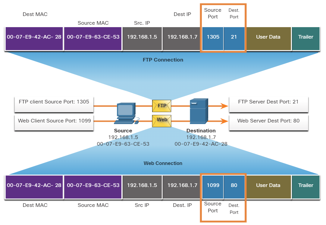
Ports
When a message is delivered using either TCP or UDP, the Protocols and services requested are identified by a port number.
What are well-known ports?
These are standardized ports assigned by IANA (Internet Assigned Numbers Authority) for widely used services and protocols.
- Range: 0 – 1023
- Assigned to common protocols (HTTP, HTTPS, FTP, SSH, DNS, etc.)
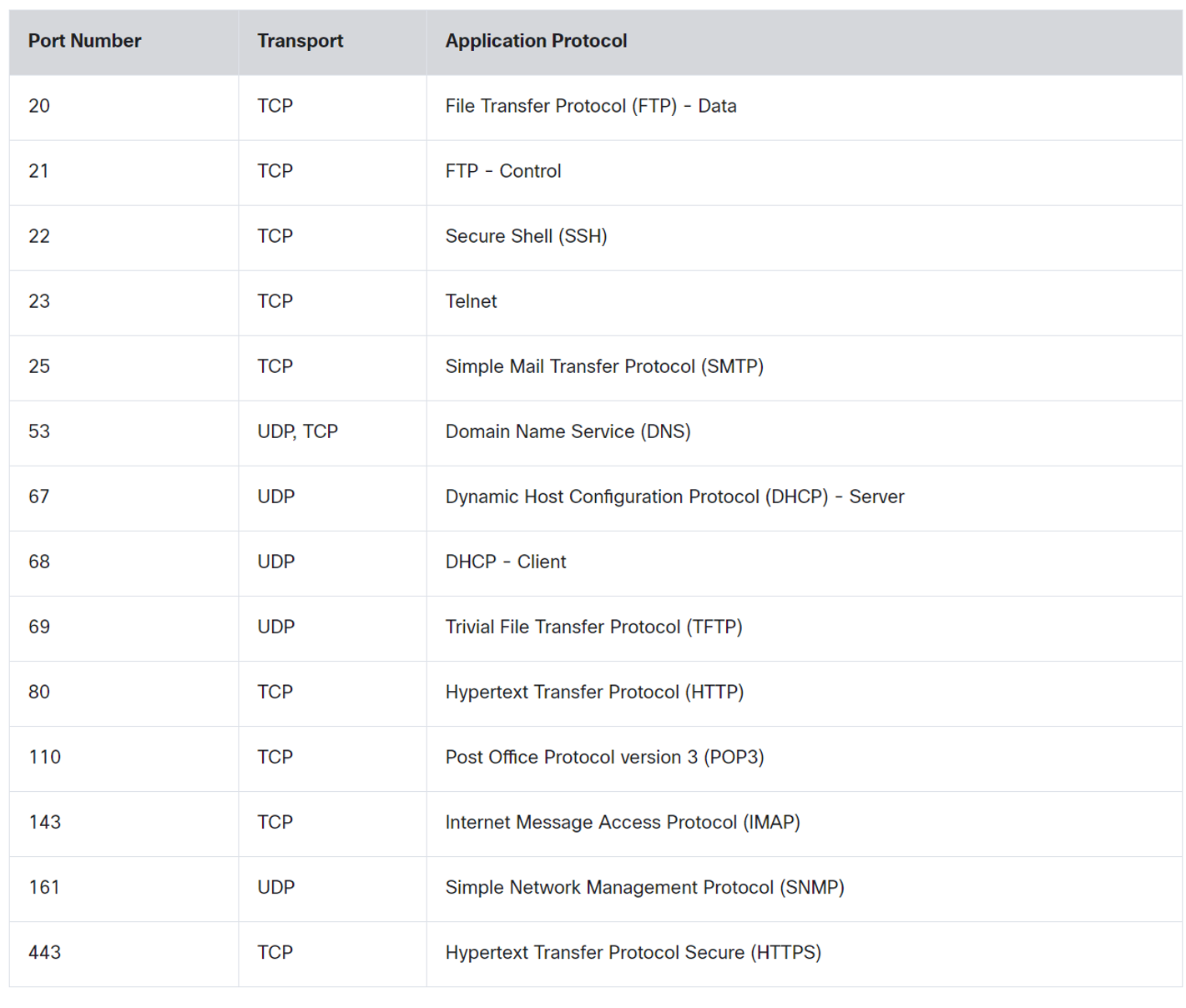
💡 DNS uses Both TCP and UDP. DNS uses UDP when clients send requests to a DNS server. However, communication between DNS servers always uses TCP.
💡 POP3: used to retrieve emails from a mail server and delete them from the mail server.
IMAP: used to retrieve emails from a mail server without deleting them on the server.SMTP: Used by an email client to send emails.
IMAP: used to retrieve emails from a mail server without deleting them on the server.
SMTP: Used by an email client to send emails.
What are registered ports?
These ports are assigned by IANA to specific software applications and services that are not as universal as Well-Known Ports but are still used widely.
- Range: 1024 – 49151
- Used by specific applications (e.g., MySQL, RDP, VoIP services).
Register port used by Both TCP / UDP
| Name | port |
| Ms SQL | 1433 |
| WAP | 2948 |
What are Dynamic Ports?
Temporary ports are used by client devices for outgoing connections.
- Range: 49152 – 65535
- Not registered with IANA; used randomly for short-lived communication.
| concept | Description |
| Same-layer interaction on different computers | The two computers use the protocol to communicate with the same layer on another computer. the protocol defines a header that communicates what each computer wants to do. |
| Adjacent(uh·jay·snt) نزیک-layer interaction on the same computer | On a single Computer, one lower layer provides a service to the layer above. |
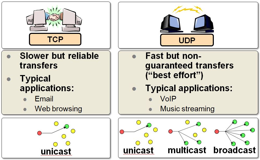
What are two characteristics of multicast transmission?
- Multicast transmission can be used by routers to exchange routing information.
- A single packet can be sent to a group of hosts.
Which two OSI model layers have the same functionality as the two layers of the TCP/IP model?
- Network
- Transport
How are port numbers used in the TCP/IP encapsulation process?
If multiple conversations occur that are using the same service, the source port number is used to track the separate conversations.
Both UDP and TCP use port numbers to provide a unique identifier for each conversation. Source port numbers are randomly generated and are used to track different conversations. Destination port numbers identify specific services by using either a default port number for the service or a port number that is assigned manually by a system administrator.
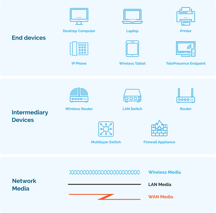
Which category of network components includes wires and cables used in a wired network?
- media
Which three elements do all communication methods have in common? (Choose three.)
- Message source.
- Message Destination.
- Message medium.
What two criteria are used to help select a network medium from various network media?
- The distance the selected medium can successfully carry a signal.
- The environment where the selected medium is to be installed.
Network Troubleshooting
A number of software utility programs are available that can help identify network problems, most of these software are provided by the operating system as a command line interface (CLI).
| IPconfig | Displays IP configuration Information on Windows Operation System. |
| IFconfig | Displays IP configuration Information on Linux Operation System. |
| Ping | Test connection to other hosts. |
| Netstat | Display network connections. |
| Tracert | Displays the route taken to the destination. |
| NSlookup | Directly queries the name server for information on a destination domain. |
ping 192.168.1.1 repeat 9999999 = ping 192.167.1.1 -t
ping -t 192.168.1.1
-t refers to continuous ping on Linux, you don’t need -t option.
ping -n 10 192.168.1.1 (windows)
ping -c 10 192.168.1.1 (Linux)
-n and -c refer to a set number of packets, by default, the number of packets is 4 echo packets.
nslookup google.com 8.8.8.8
Query a specific DNS server
nslookup 8.8.8.8
get hostname from IP
netstat -o
Display process IDs
netstat -n
-n option can be used to display IP addresses and port numbers.
netstat -p tcp
netstat -p udp
Show protocol-specific connections
netstat -aon | find "443"
Find a Process Using a Specific Port
netstat -an | find "192.168.1.1"
netstat -ano
We can use more than one option together -a -n -o
Which command can be used on a Windows host to display the routing table?
netstat -r
Which command can be used on a Windows host to display the ARP table?
arp -a
Which command can be used on a Windows host to display the routing table IPv6?
route print
Verifying Network Connectivity
Using and interpreting the output of various testing tools is often the first step in isolating the cause of a network connectivity issue. The ping command can systematically test connectivity by looking for answers to the following questions, in this order:
| Step 1. Can an end device ping itself? |
| Step 2. Can an end device ping its default gateway? |
| Step 3. Can an end device ping the destination? |
Seven-Step Troubleshooting Process
Define Problem: Define what the problem is. Problems are usually identified by a sign (e.g., the network is slow or has stopped working). Network issues may appear in many different forms, including alerts from the network management system, console messages, and user complaints. In an organization, problems are typically assigned to network technicians as trouble tickets.
Gather Information: In this step, targets (i.e., hosts, devices) to be investigated must be identified, access to the target devices must be obtained, and information gathered.
Analyze Information: Possible causes must be identified. The gathered information is interpreted and analyzed using network documentation, network baselines, searching organizational knowledge bases, searching the internet, and talking with other technicians.
Eliminate Possible Causes: If multiple causes are identified, then the list must be reduced by progressively eliminating possible causes to eventually identify the most probable cause. Troubleshooting experience is extremely valuable to quickly eliminate causes and identify the most probable cause.
Purpose Hypothesis: When the most probable cause has been identified, a solution must be formulated. At this stage, troubleshooting experience is very valuable when proposing a plan.
Test Hypothesis: Before testing the solution, it is important to assess the impact and urgency of the problem. For instance, could the solution have an adverse effect on other systems or processes? The severity of the problem should be weighed against the impact of the solution. For example, if a critical server or router must be offline for a significant amount of time, it may be better to wait until the end of the workday to implement the fix.
Solve the Problem: When the problem is solved, inform the users and anyone involved in the troubleshooting process that the problem has been resolved. Other IT team members should be informed of the solution. It is important to properly document the cause and solution as this can assist other support technicians to prevent and solve similar problems in the future.
#
Establish a Network Baseline
A baseline is used to establish normal network or system performance to determine the “personality” of a network under normal conditions.
A network baseline should answer the following questions:
- How does the network perform during a normal or average day?
- Where are the most errors occurring?
- What part of the network is most heavily used?
- What part of the network is least used?
- Which devices should be monitored and what alert thresholds should be set?
- Can the network meet the identified policies?
#
Structured Troubleshooting Methods
Bottom-Up
In bottom-up troubleshooting, you start with the physical layer and the physical components of the network.
The disadvantage of the bottom-up troubleshooting approach is that it requires that you check every device and interface on the network until the possible cause of the problem is found.
Top-Down
top-down troubleshooting starts with the end-user applications and moves down through the layers of the OSI model until the cause of the problem has been identified.
Divide-and-Conquer
The network administrator selects a layer and tests in both directions from that layer.
In divide-and-conquer troubleshooting, you start by collecting user experiences of the problem, document the symptoms and then, using that information, make an informed guess as to which OSI layer to start your investigation.
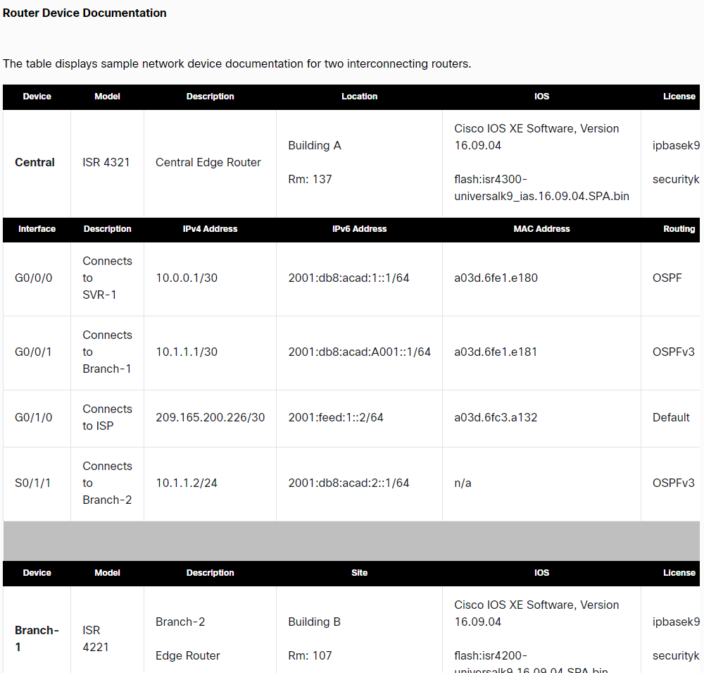
Network Device Documentation
Network Topology and Architectures
SOHO
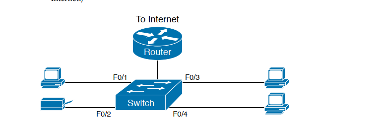
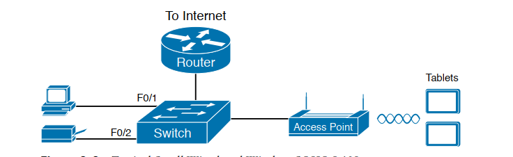
- Small office/home office (SOHO) LAN, use only Ethernet LAN technology.
- Switch and routes may be combined.
Wan
Private WAN infrastructure: Service providers may offer dedicated point-to-point leased lines, circuit-switched, such as PSTN or ISDN, and packet-switched links, such as Ethernet Wan, ATM, or frame Relay.
Public WAN Infrastructure: Service providers provide Internet access using broadband services such as DLS, cable, and satellite access, broadband connections. Data travelling between corporate sites over the public Wan infrastructure should be protected by using a VPN.
Private WAN: Leased Line
A point-to-point link is used to provide a pre-established WAN communication path from the customer premises to the provider network. Point-to-point Lines are usually leased from a service provider and are called leased lines.
Private Wan: Frame Relay
is a simple layer 2 non-broadcast multi-access(NBMA)
WAN technology is used to interconnect enterprise LANs. A single router interface can be used to connect multiple sites.
Note: old and useless and fast.
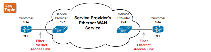
Private WAN: Ethernet WAN
Newer Ethernet standards using fiber-optic cables have made Ethernet a reasonable WAN access option. IEEE 1000BASE-LX standard supports fiber-optic cable lengths of 5km, white IEEE 1000BASE-ZX standard supports cable lengths up to 70 Km.
The Ethernet WAN Types:
- Metropolitan Ethernet(MetroE)
- Ethernet over MPLS (EoMPLS) popular
- Virtual Private LAN Service(VPLS)
Note: when you see IEEE it’s purpose of layer 1 or 2 technology , IEEE organization made Layer 1 and layer 2 as a standard
Private WAN: MPLS
- Multiprotocol Label Switching(MPLS) is a multiprotocol high-performance WAN technology that directs data from one router to the next. MPLS is based on short path labels rather than IP network addresses.
- It is multiprotocol, has the ability to carry any payload including IPV4, IPv6, Ethernet, ATM, DSL, and frame relay traffic. It uses labels that tell a router what to do with a packet. The labels identify paths between distant routes rather than endpoints, and while MPLS actually routes IPv4 and IPv6 packets, everything else is switched.
- MPLS can deliver any type of packet between sites. MPLS can encapsulate packets of various network protocols. It supports a wide range of WAN technologies including T-carrier/E-carrier links, Carrier Ethernet, ATM, Frame relay, and DSL.
Note: MPLS is described as layer 2.5.
The MPLS layer lies between layers 2 and 3 of the model ie the Data Link and the Network Layer. That’s why it is also known as the 2.5 layer protocol or “shim” protocol.
The MPLS header is 32 bits.
Private WAN: VSAT
- A very small aperture terminal(VSAT) is a solution that creates a private WAN using satellite communications. A VSAT is a small satellite dissimilar to those used for home internet and TV. VSATs create a private WAN while providing connectivity to remote locations.
Public WAN
- DSL, ADSL, or cables
- Wireless(3G/4G, LTE, or WIMAX)
- VPN ( Site to Site VPN)
Introducing Cisco IOS
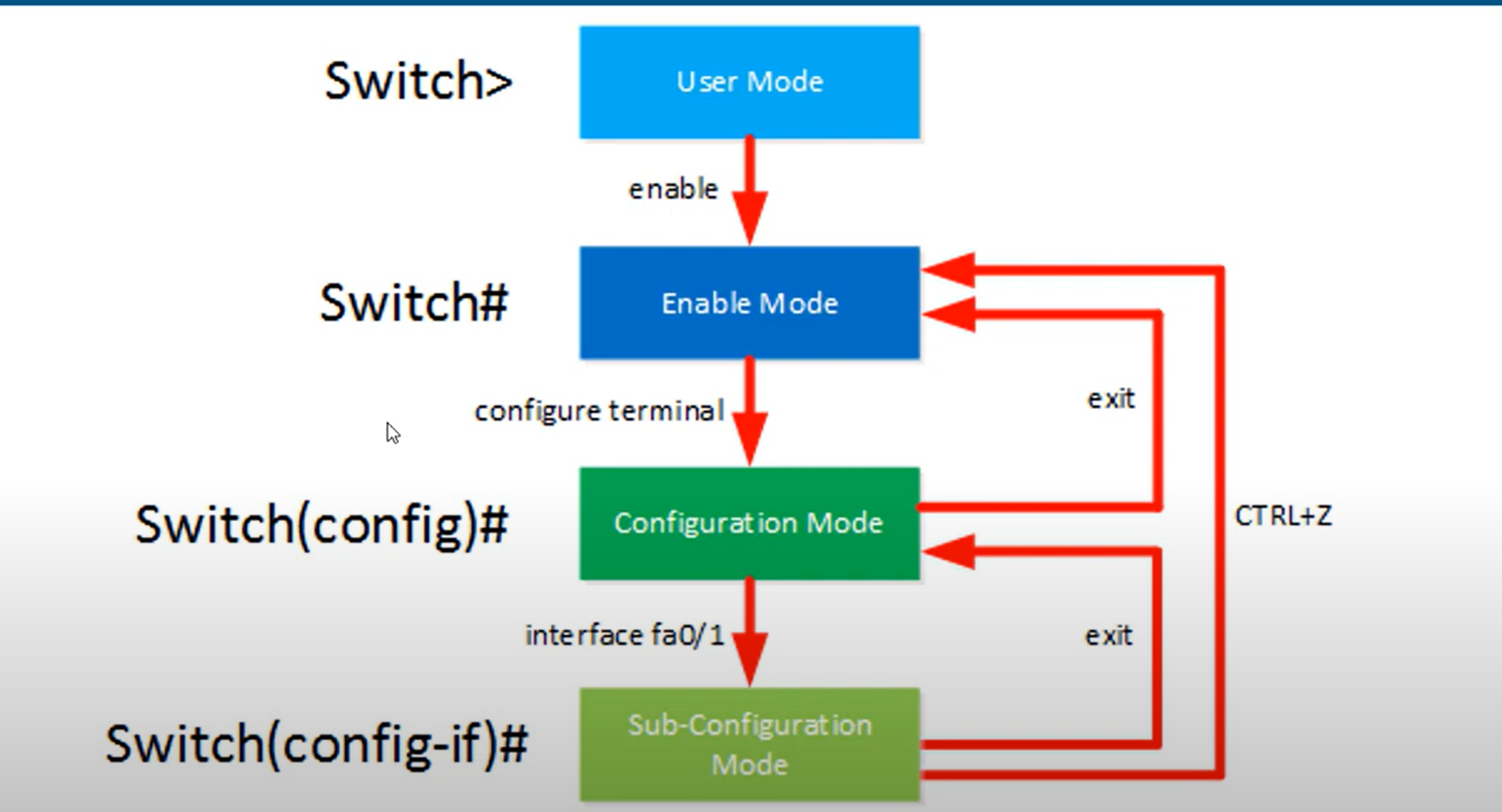
- User EXEC Mode - This mode has limited capabilities but is useful for basic operations. It allows only a limited number of basic monitoring commands but does not allow the execution of any commands that might change the configuration of the device. The user EXEC mode is identified by the CLI prompt that ends with the > symbol.
- Privileged EXEC Mode - To execute configuration commands, a network administrator must access privileged EXEC mode. Higher configuration modes, like global configuration mode, can only be reached from privileged EXEC mode. The privileged EXEC mode can be identified by the prompt ending with the # symbol.
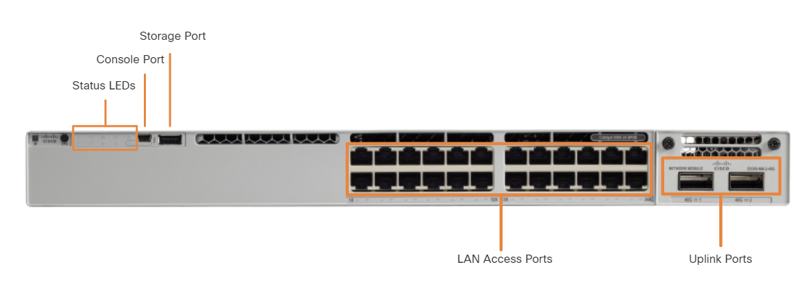
An uplink port is a switch port designed to connect to another switch, router, or modem for network expansion. Traditionally, uplink ports required straight-through cables to connect to other network devices.
🔹 Common Uses:
- Connecting switch-to-switch (e.g., trunk links).
- Connecting a switch to a router (router-on-a-stick).
- Connecting to an ISP modem or fiber uplink.
🔹 Labeling on Cisco Switches:
- Typically labeled G0/1, G1/1, or GigabitEthernet 1/0/1.
A normal port (also called an access port) is a standard switch port used to connect end devices like PCs, printers, and IP phones.
Rollover Cable: Used for device configuration via the console port.
Crossover Cable: Used for network connections between similar devices (e.g., switch-to-switch, PC-to-PC in older networks)
Note:
- Use the straight cable to connect two different devices.
- Use the crossover cable for connecting two of the same type.
Today, all new devices of different types can be connected through a straight cable
###
RAM: RAM stores running configuration, CDP information, ARP memory, routing table, etc.
NVRAM: This memory stores the system configuration by typing the copy run start command.
FLASH: The FLASH memory is the router's IOS (Internetwork Operating System) memory.
ROM: Stands for Read Only Memory. This memory stores the boot or bootstrap of the system
- Power supply
- Fan
- Protection for WAN (WIC) or high-speed WIC (HWIC) interface card
- Dynamic synchronous RAM (SDRAM) is used to keep the configuration running and routing tables.
- Non-volatile RAM (NVRAM) and boot flash memory are used to store the ROMMON boot code and NVRAM data.
- CPU
- The connection of the advanced integration module (AIM) downloads functions that demand a lot from the processor, such as encryption from the main CPU.
- Protection for WAN (WIC) or high-speed WIC (HWIC) interface card
Access to Cisco IOS CLI
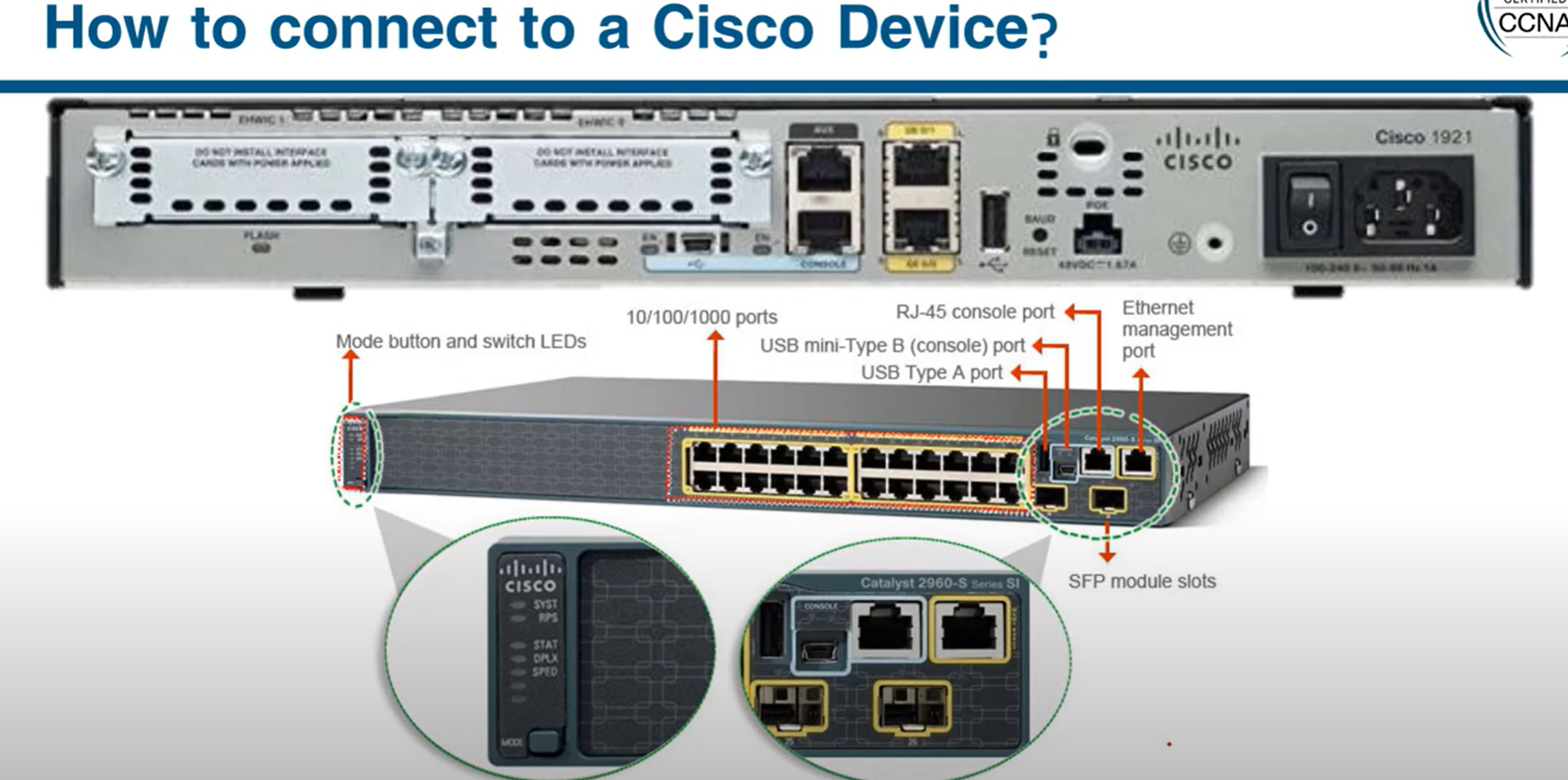
Before entering any commands, we need access to the CLI. Here are three options:
- Console - Uses a low-speed serial or USB connection to provide direct connect, out-of-band management access to a Cisco device.
- SSH - Method for remotely accessing a CLI session across an active network interface, including the management interface.
- AUX port - Used for remote management of the router using a dial-up telephone line and modem.
- HTTP/HTTPS - Some routers and switches support web-based management connections, allowing administrators access using HTTP.
💡 To securely configure and monitor a router from a remote location, you use HTTPS to access the router's web-based management interface, ensuring that all transmitted data is encrypted.
In-Band and Out-of-Band Device Management
| Aspect | In-band Management | Out-of-band Management |
| Network | Same as user traffic network | Dedicated, separate management network |
| Access Methods | SSH, Telnet, HTTP/HTTPS, SNMP | Serial console, dedicated interfaces (e.g., iLO, DRAC) |
| Security | Risk of exposure to attacks | More secure due to isolation from user traffic |
| Availability | Dependent on network availability | Available even if the main network is down |
| Cost | Lower cost, no need for extra infrastructure | Higher cost due to separate network setup |
| Convenience | Easier to configure and access | Less convenient, requires additional setup |
out-of-band management example:
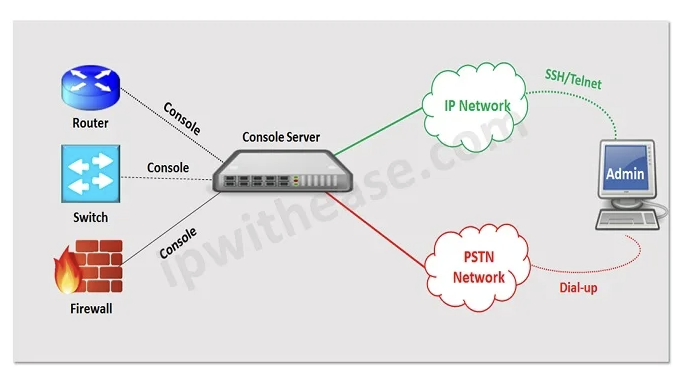
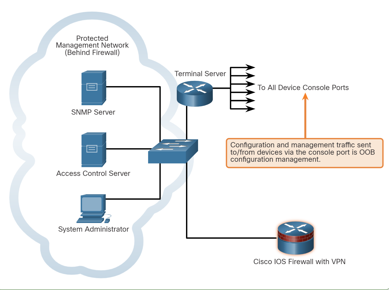
💡 A terminal server and a console server a hardware or virtual devices used by network and system administrators to provide secure, remote access to the console ports (usually serial ports) of network equipment such as Routers, switches, servers, and firewalls.
Guidelines for OOB Management:
- Provide the highest level of security when using console ports and management interfaces.
- Mitigate the risk of passing insecure management protocols over the production network.
Guidelines for In-Band Management:
- Apply to devices that need to be managed or monitored.
- Use IPsec, SSH, or SSL when possible.
- Decide whether the management channel needs to be open at all times.
WebUI Configuration Example
Cisco IOS-XE routers and Catalyst switches come with a web-based management interface known as the WebUI or web GUI (Graphical User Interface). This tool allows administrators to configure and monitor the device using a web browser, offering a more visual approach to network management.
To configure a Cisco router or switch for WebUI access, you will need a username command configured and some ip http commands. In addition, securing WebUI with an access control list is recommended. For example, the following configuration allows secure WebUI access to R1 through the 192.168.1.1/24 interface by any user on the 192.168.1.0/24 network.
R1(config)# interface GigabitEthernet0/0/1
R1(config-if)# ip address 192.168.1.1 255.255.255.252
R1(config-if)# no shutdown
R1(config)# exit
R1(config)# username admin privilege 15 secret cisco123
R1(config)# no ip http server
R1(config)# ip http secure-server
R1(config)# ip http authentication local
R1(config)# access-list 10 permit 192.168.1.0 0.0.0.255
R1(config)# ip http access-class ipv4 10
| Creates a user named "admin" with full administrative access (privilege 15) and sets the password to "cisco123" (encrypted). |
| no ip http server: Disables the standard HTTP server. |
| ip http secure-server: Enables the HTTPS server. |
| Uses the local username and password database for HTTP authentication. |
| Creates an ACL (numbered 10) permitting access from devices in the IP range 192.168.1.0 to 192.168.1.25 |
| ip http access-class ipv4 10: Applies the ACL (numbered 10) to restrict HTTP access to the specified IP range. |
💡 IOS defines two privilege levels by default: 0 (user mode) and 15 (privileged mode).
Cloud Device Management
Cisco offers two advanced cloud applications that provide comprehensive graphical interfaces: Cisco Catalyst Center (formerly Cisco DNA Center) and Cisco Meraki Dashboard.
- Cisco Catalyst Center: Large, complex networks requiring detailed oversight and control.
- Small to medium-sized businesses or distributed networks.
Console Cabling
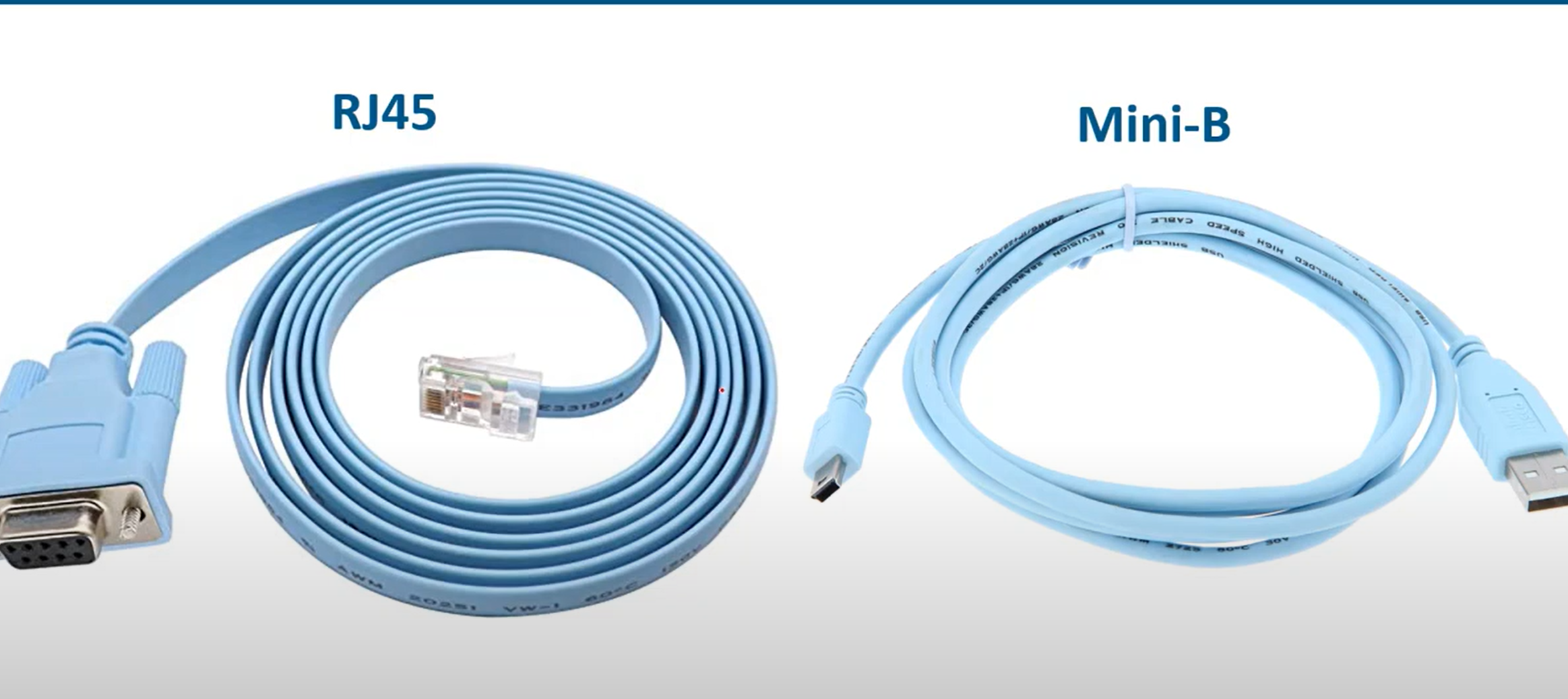
💡 Routers and switches have a blue colour cable used to connect to the console port to pc and perform configuration
How to save the Configuration?
💡 Copy running-config startup-config
then enter
WR (tab)
enter
Copy running-config startup-config
then enter
WR (tab)
enter
How to remove the saved configuration in NVRAM and reset the router?
💡 write erase
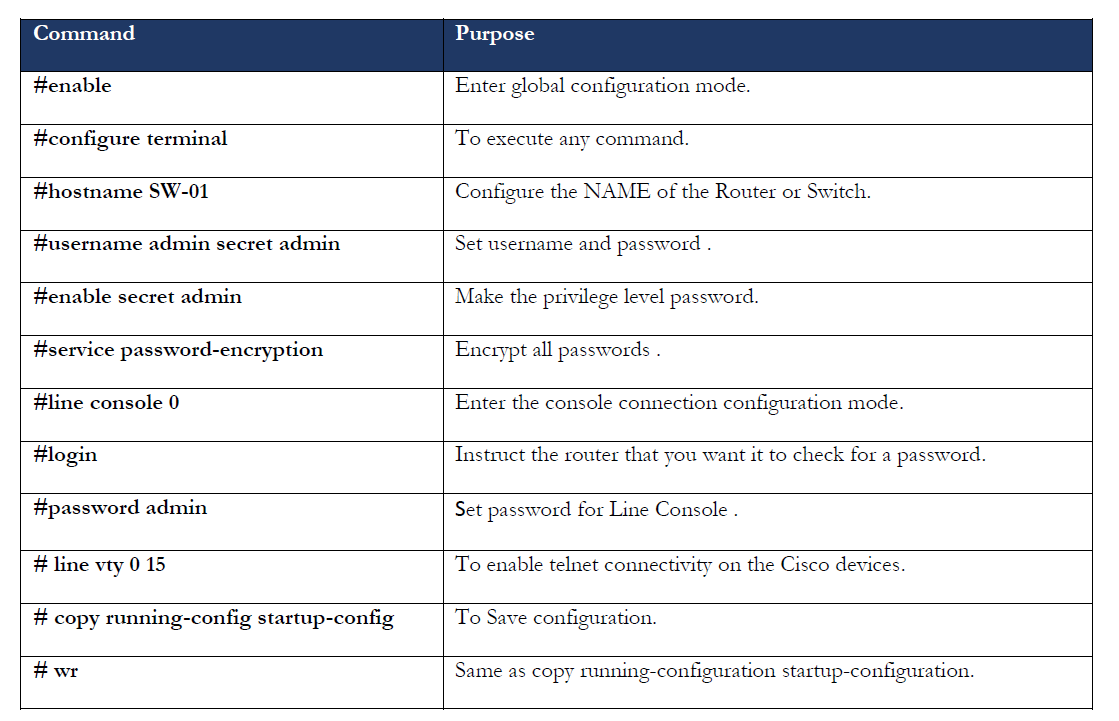
Changing Host Name and adding a banner to Cisco Devices
hostname: change the name of the router example:
hostname ISU-R1
Banner: A simple message shows up when we log in to the router through the terminal.
banner motd $ don’t access to this router without sysadmin permission $
💡
Switch(config)#service password-encryption
The service password-encryption command will encrypt every plaintext password.
Set password to Privilege (global) mode
To set a password to privilege mode, use the commands below:
💡 ISU-R1(config)# enable password [your-password]
When we use show running-configuration command, the password shows as plain text. Use this command to set a secure password
💡 ISU-R1(config)# enable secret [your-password]
To remove a password or a secret, just add no before the command, for example:
no enable password
Set password to User EXEC mode
To set a password for the router, the user should enter the password before the user mode opens and connect the cabling using the commands below:
line con 0 (line port always is zero)
line aux 0 (both console and aux port used to router configuration, aux port working as a backup port when the console port is not working )
line vty 0 4 “vty” (stands for Virtual teletype: it is a virtual line you can virtually configure the router)
Note: 0 4 means 5 connections can be established at the same time.
Router(config)#line console 0

Router(config-line)#password your-password

Router(config-line)#login
When you run this command, it shows the running-config
The console line should show logging, which means a login is required to enter the router and perform configuration
line con 0
password rebar
login
!
line aux 0
!
line vty 0 4
login
!
Set the Username and password account to the router account
If an employee leaves the company, others are required to change the password on all routers. Adding individual user accounts is a better approach to address this issue.
Router(config)#userame your-username secret your-password
Router(config)#line con 0

Router(config-line)#login local //using local databse to check username and password
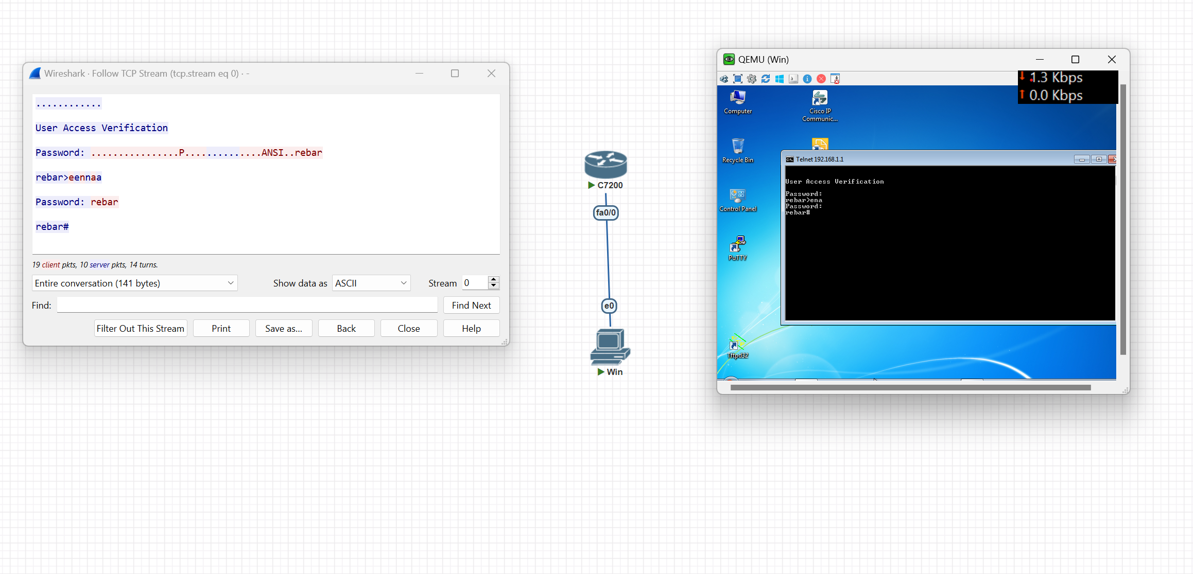
Virtual login to the router (Telnet)
R1-isu(config)#line vty 0 4
R1-isu(config-line)#password rebar
R1-isu(config-line)#login // if you want to login with only password
R1-isu(config-line)#login local  // use this command if you want to loing with user and passowrd
After adding a password, you can log in to the router through Telnet
telnet IP-address(router)
Then enter the password and log in to the router
💡 Note: Telnet is less secure because it transfers data as plain text without encryption
R1-isu(config)#no ip domain-lookup
Use the command above when you write a command by mistake, as it takes a lot of time
Translating "ded"...domain server (255.255.255.255)
Virtual login to the router (SSH)
Step 1. Verify SSH support.
Use the show ip ssh command to verify that the switch supports SSH. If the switch is not running an IOS that supports cryptographic features, this command is unrecognized.
Step 2. Configure the IP domain.
isu-R1(config)#ip domain-name [Enter Your Domain Name]
isu-R1(config)#ip domain-name ISU-Airport
### Step 3. Generate RSA key pairs.
isu-R1(config)#crypto key generate rsa
After entering the set key length of encryption recommended value is 1024 or 2048
isu-R1(config)#ip ssh version 2 [Version 2 is the newest version of SSH]
###
Step 4. Configure user authentication.
The SSH server can authenticate users locally or use an authentication server.
- Username and password Account
isu-R1(config)#userame your-username secret your-password
### Step 5. Configure the vty lines.
isu-R1(config)#line vty 0 4
isu-R1(config-line)#transport input ssh
with transport input, you can choose which protocol can be used for virtual configuration like telnet, SSH… etc.
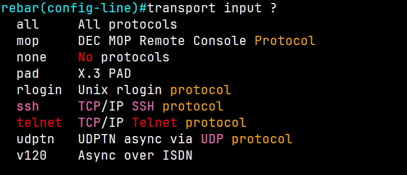
R1-isu(config-line)#login local // use this command if you want to loing with user and passowrd
Change interface speed and Duplex
When we have multiple switches, if we want to change the speed between the switches, use the commands below
For example, we want to change the speed ISU Switch to 10 bits from auto speed
ISUSW#show interfaces status
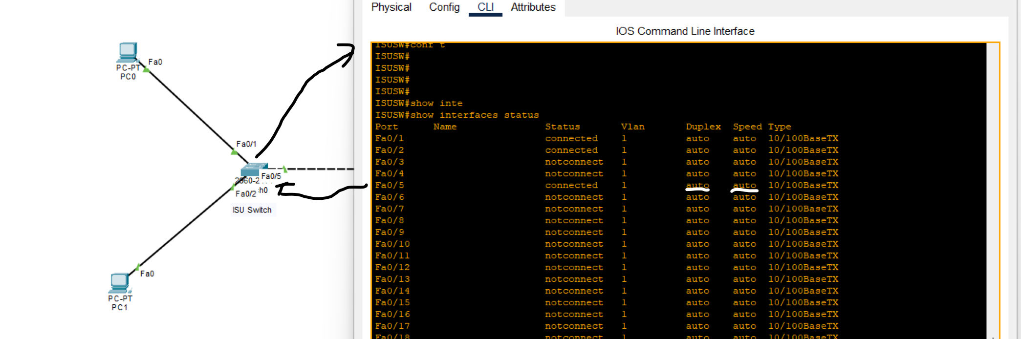
As you can see, FastEthernet0/5 speed is auto, and duplex by default is auto.
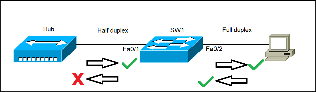
What is a Duplex?
- means the ability to send and receive data or signals between two points.
- Full-duplex all nodes can send and receive data on their port at the same time. The following types of connections can use full duplex: Switch to Switch, Switch to Host, Host to Host
- Half-duplex: When one node sends data and can’t receive data at the same time. The following types of connections can use half duplex: Hub to Hub, Switch to Hub
- Type:10/100baseTx: it means 10 (Mbps) megabit / 100 (Mbps) megabit per second
ISUSW(config-if)#speed 100
When we changed one router's speed to 100 Mbps, nothing happened to the next router because its speed was set to auto by default. However, when we changed the second router's speed from auto to 10 Mbps, an error occurred due to the mismatch in speeds between the two connected lines.
How to change duplex
ISUSW(config-if)#duplex full
EBLSW(config-if)#duplex full
💡 Both switches should have the same duplex setting.
Note: B**y default, duplex is set to auto. However, it's generally recommended to change it to a full duplex for optimal performance.**
Packet Capturing with Wireshark
ARP(Address Resolution Protocol)
is a network protocol used to find out the hardware (MAC) address of a device from an IP address It is used when a device wants to communicate with some other device on a local network (for example on an Ethernet network that requires physical addresses to be known before sending packets).
ARP request packets are sent to the broadcast addresses (FF:FF:FF:FF:FF:FF for the Ethernet broadcasts and 255.255.255.255 for the IP broadcast).
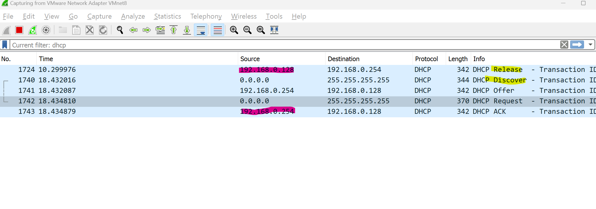
We can track computer requests when the process of releasing and renewing IP addresses occurred.
CMD → ipconfig /release the ipconfig /release
ipconfig /release sends a command to the DHCP server instructing it to dump the network configuration and then deletes the current network configuration for all adapters (IP address, DNS servers, gateway, etc).
/renew will instruct your computer to request a new IP address from the DHCP server as well as DNS, gateway, and whatever other information the DHCP server is set to configure.
MAC Addresses and Basic Switching Concepts
What is an Ethernet Frame?
An Ethernet frame is a data unit used in computer networks to transmit information between devices on a local area network (LAN). It contains the source and destination MAC addresses, payload data, and error-checking information, forming the basic structure for communication in Ethernet networks.
Ethernet protocols define how data is formatted and transmitted over a wired network.
Ethernet is defined by data link layer and physical layer protocols.
Preamble: It helps synchronize the receiving device’s clock with the incoming data.
SDF: marks the end of the preamble and the beginning of the rest of the frame.
Destination MAC: identifies the receiving device.
Source MAC: identifies the sending device.
Type: This indicates the length of the entire Ethernet frame (Usually IPv4 or IPv6).
FCS: Frame check sequence is used to detect errors in a frame.
Which Ethernet frame field indicates the beginning of an Ethernet frame?
Preamble and SFD
What is a MAC Address?
Media Access Control(MAC): the physical address, which uniquely identifies each device on a given network. To communicate between two networked devices, we need two addresses: an IP address and a MAC address**. It is assigned to the NIC** (Network Interface Card) of each device that can be connected to the internet.
It is globally unique: it means two devices cannot have the same MAC address. It is represented in a hexadecimal format on each device, such as 00:0a:95:9d:67:16.
It is 12 digits, 48 bits (6 bytes) long, out of which the first 24 bits(first 6 digits) are used for OUI(Organization Unique Identifier), for example (3C-8B-7F), and 24 bits(second 6 digits) for NIC/vendor-specific.
It works on the data-link layer of the OSI model.
IPV4 → uses ARP protocol to associate the logical address with the MAC Address.
IPV6 → uses ICMPV6 Neighbor Discovery(ND) to associate the logical address with the MAC Address.
Why should the MAC address be unique in the LAN network?
If a LAN network has two or more devices with the same MAC address, that network will not work.
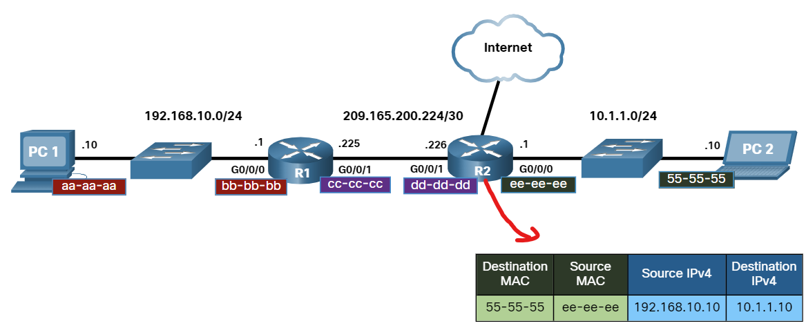
There are two primary addresses assigned to a device on an Ethernet LAN:
- Physical Address (The MAC address) - used for NIC-to-NIC communication on the same Ethernet network.
- Logical Address (the IP address) - used to send the packet from the source device to the destination device. The destination device may be on the same network as the source, or it may be on a remote network.
Destination on the Same network
Layer 2 physical addresses (i.e., Ethernet MAC addresses) are used to deliver the data link frame with the encapsulated IP packet from one NIC to another NIC that is on the same network. If the destination IP address is on the same network, the destination MAC address will be that of the destination device.
Destination on the Remote network
When the destination IP address(IPv4 or IPV6) is on a remote network, the destination MAC address will be the address of the host default gateway(i.e., the router interface).
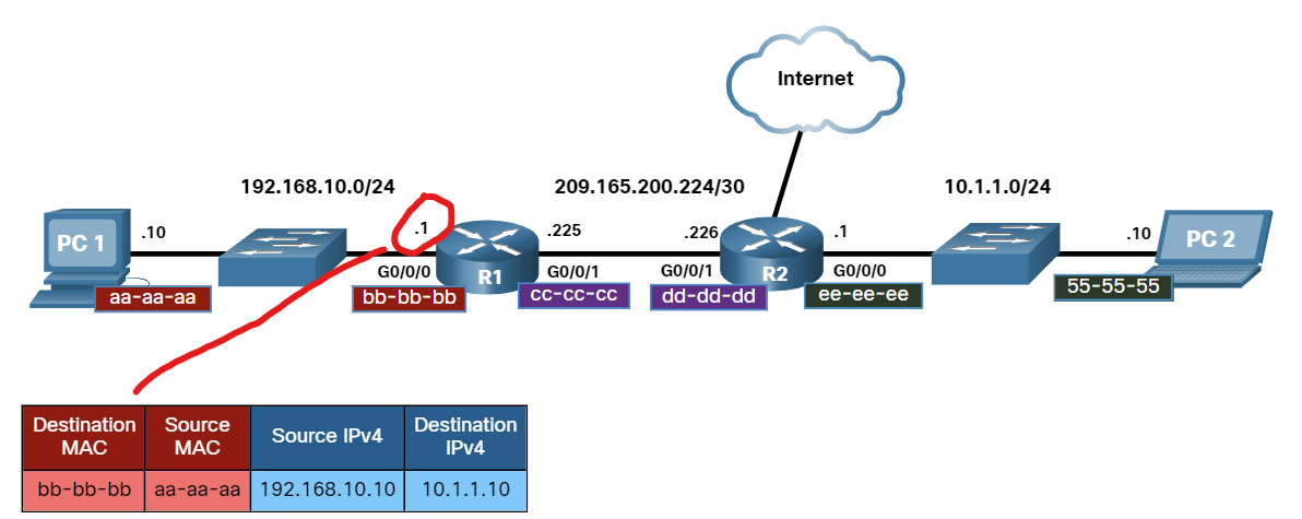
Routers examine the destination IPv4 address to determine the best path to forward the IPv4 packet. When the router receives the Ethernet frame, it de-encapsulates the Layer 2 information. Using the destination IPv4 address,g it determines the next-hop device and then encapsulates the IPv4 packet in a new data link frame for the outgoing interface.
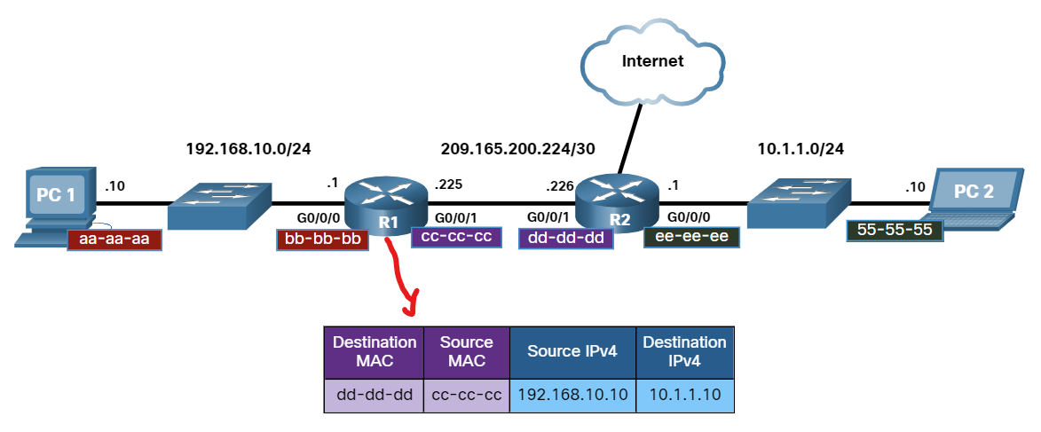
Along each link in a path, an IP packet is encapsulated in a frame. The frame is specific to the data link technology that is associated with that link, such as Ethernet. If the next-hop device is the final destination, the destination MAC address will be that of the device's Ethernet NIC, as shown in the figure.
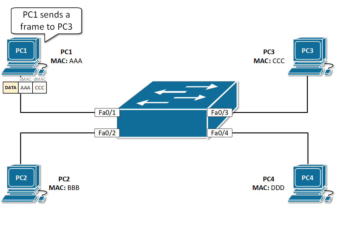
Ethernet LAN Switching
An Ethernet switch examines its MAC address table to make a forwarding decision for each frame.
Switch Learning and Forwarding
- Learn Every frame that enters a switch is checked for new information to learn. It does this by examining the source MAC address of the frame and the port number where the frame entered the switch. If the source MAC address does not exist, it is added to the table along with the incoming port number.
- Forwarding If the destination MAC address is a unicast address, the switch will look for a match between the destination MAC address of the frame and an entry in its MAC address table. If the destination MAC address is in the table, it will forward the frame out the specified port. If the destination MAC address is not in the table, the switch will forward the frame out all ports except the incoming port. This is called an unknown unicast.
Which network device has the primary function of sending data to a specific destination based on the information found in the MAC address table?
- switch
Ethernet switches add entries to their MAC address table based on what field of the Ethernet frame?
- source MAC address
When a switch receives an Ethernet frame and the destination MAC address of that frame is not in its MAC address table, the switch will:
- Forward the frame out of all ports except in the incoming port.
What addressing information is recorded by a switch to build its MAC address table?
- The source Layer 2 address of incoming frames
What is one function of a Layer 2 switch?
- Determines which interface is used to forward a frame based on the destination MAC address
Which information does a switch use to keep the MAC address table information current?
- The source MAC address and the incoming port.
What will a host on an Ethernet network do if it receives a frame with a unicast destination MAC address that does not match its own MAC address?
- It will discard the frame.
What kind of frame does a switch flood out of all interfaces except the one it was received on?
- Unknown Unicast
What happens to runt frames received by a Cisco Ethernet switch? • The frame is dropped.
ARP(Address Resolution Protocol)
ARP is a network protocol used to find out the hardware (MAC) address of a device from an IP address ( layer 3 address). It is used when a device wants to communicate with another device on a local network (for example, on an Ethernet network that requires physical addresses to be known before sending packets).
ARP request packets are sent to the broadcast addresses (FF:FF:FF:FF:FF: FF for the Ethernet broadcasts and 255.255.255.255 for the IP broadcasts).
Consists of two messages:
ARP Request is Broadcast = sent to all hosts on the network.
ARP Replay is Unicast = sent only to one host (The host that sent the request).
ARP provides two basic functions:
- Resolving IPv4 addresses to MAC addresses.
- Maintaining a table of IPv4 to MAC address mappings.
The sending device will search its ARP table for a destination IPv4 address and a corresponding MAC address.
- If the packet’s destination IPv4 address is on the same network as the source IPv4 address, the device will search the ARP table for the destination IPv4 address.
- Suppose the destination IPv4 address is on a different network from the source IPv4 address. In that case, the device will search the ARP table for the IPv4 address of the default gateway., It uses the ARP process to determine the MAC address of the default gateway.
- The ARP table temporarily saves (caches) the mapping for the devices on the LAN.
- The packet is dropped if no device responds to the ARP request because a frame cannot be created.
- Entries in the ARP table are time-stamped. If a device does not receive a frame from a particular device before the timestamp expires, the entry for this device is removed from the ARP table.
💡 Note: IPv6 uses a similar process to ARP for IPv4, known as ICMPv6 Neighbor Discovery (ND). IPv6 uses neighbor solicitation and neighbor advertisement messages, similar to IPv4 ARP requests and ARP replies.
On a Cisco router, the show ip arp command is used to display the ARP table
R1# show ip arp
On a Windows PC, the arp –a command is used to display the ARP table
C:∖Users∖PC> arp -a
ARP Security
In some cases, the use of ARP can lead to a potential security risk. A threat actor can use ARP spoofing to perform an ARP poisoning attack. This is a technique used by a threat actor to reply to an ARP request for an IPv4 address that belongs to another device, such as the default gateway, as shown in the figure. The threat actor sends an ARP reply with its own MAC address. The receiver of the ARP reply will add the wrong MAC address to its ARP table and send these packets to the threat actor.
Enterprise-level switches include mitigation techniques known as dynamic ARP inspection (DAI)**.**
We can track computer requests when the process of releasing and renewing IP addresses occurs.
CMD → ipconfig /release the ipconfig /release
ipconfig /release sends a command to the DHCP server instructing it to dump the network configuration and then deletes the current network configuration for all adapters (IP address, DNS servers, gateway, etc).
/renew will instruct your computer to request a new IP address from the DHCP server as well as DNS, gateway, and whatever other information the DHCP server is set to configure.
ARP request packets are sent to the broadcast addresses (FF:FF:FF:FF:FF:FF for the Ethernet broadcasts and 255.255.255.255 for the IP broadcasts).
We can track computer requests when the process of releasing and renewing IP addresses occurs.
CMD → ipconfig /release the ipconfig /release
ipconfig /release sends a command to the DHCP server instructing it to dump the network configuration and then deletes the current network configuration for all adapters (IP address, DNS servers, gateway, etc).
/renew will instruct your computer to request a new IP address from the DHCP server as well as DNS, gateway, and whatever other information the DHCP server is set to configure.


MAC Address Transmission types?
Unicast MAC address:
The Unicast MAC address represents the specific NIC on the network. A Unicast MAC address frame is only sent out to the interface that is assigned to a specific NIC and hence transmitted to the single destination device. If the LSB (least significant bit) of the first octet of an address is set to zero, the frame is meant to reach only one destination NIC.
Multicast MAC Address
Multicast addresses enable the source device to transmit a data frame to multiple devices or NICs. In Layer-2 (Ethernet) Multicast address, the LSB (least significant bit) or the first 3 bytes of the first octet of an address is set to one and reserved for the multicast addresses. The rest 24 bits are used by the device that wants to send the data in a group. The multicast address always starts with the prefix 01-00-5E.
Broadcast MAC address
It represents all devices within a Network. In broadcast MAC address, Ethernet frames with ones in all bits of the Destination address (FF-FF-FF-FF-FF-FF) are known as a broadcast address . All these bits are the reserved addresses for the broadcast. Frames that are destined with MAC address FF-FF-FF-FF-FF-FF will reach every computer belonging to that LAN segment. Hence if a source device wants to send the data to all the devices within a network, it can use the broadcast address as the destination MAC address.
How to find a MAC Address vendor?
Use the website below to find the vendor who creates the NIC card:
Practice MAC Address
When we connect two or more devices through a switch and run this command below in the switch
ISUSW1#show mac address-table
As you can see, no MAC address record is found because no data was transmitted over the switch.
After executing the ping command from one PC to another, run the current command on the switch.
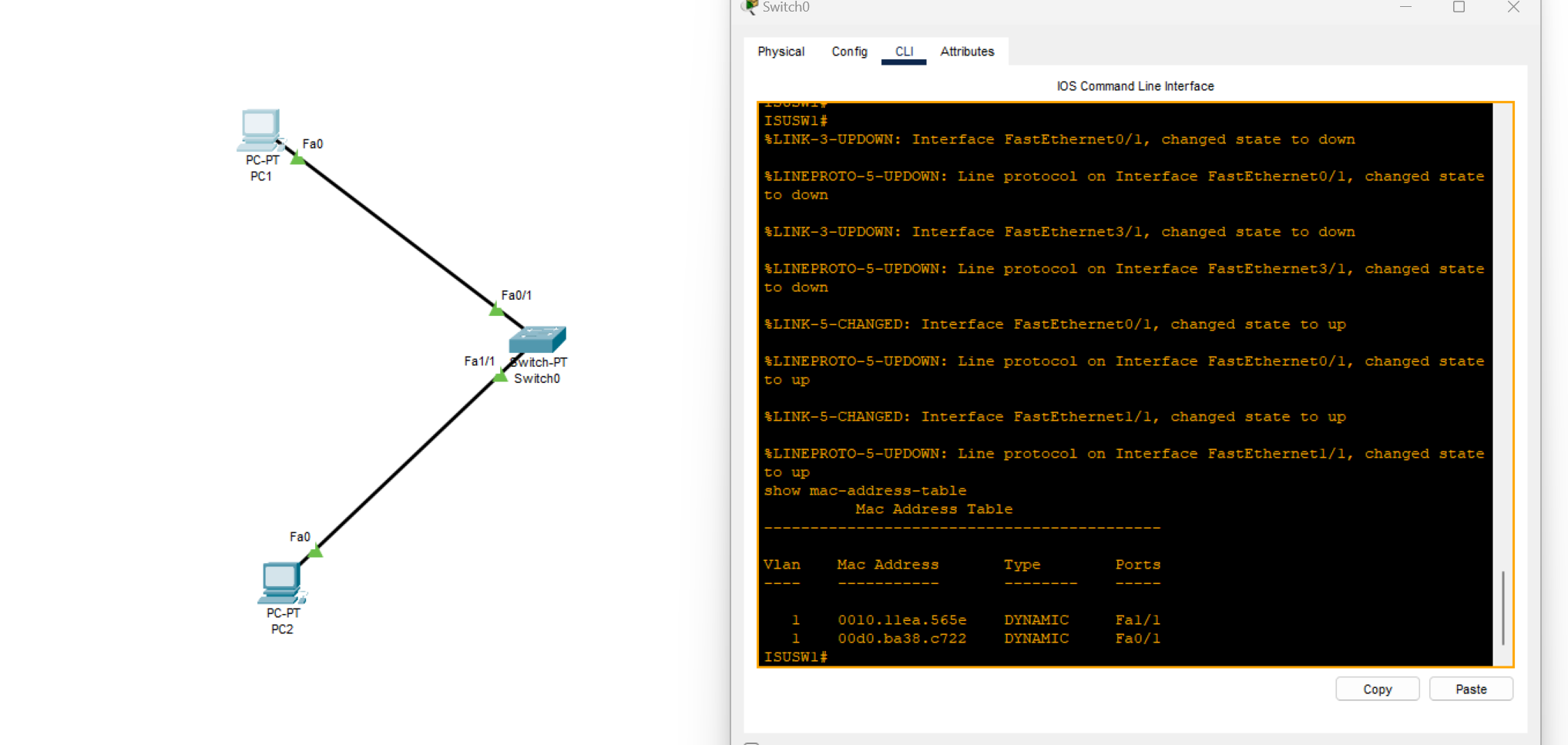
Now, all MAC addresses are connected to the switch and visible because the switches have a self-learning feature.
When we have two connected switches, as shown in the images below:
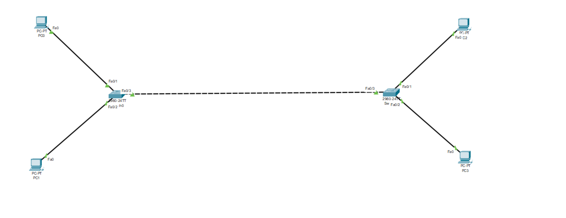
While sending a ping message from one pc to another pc connected to the other switch
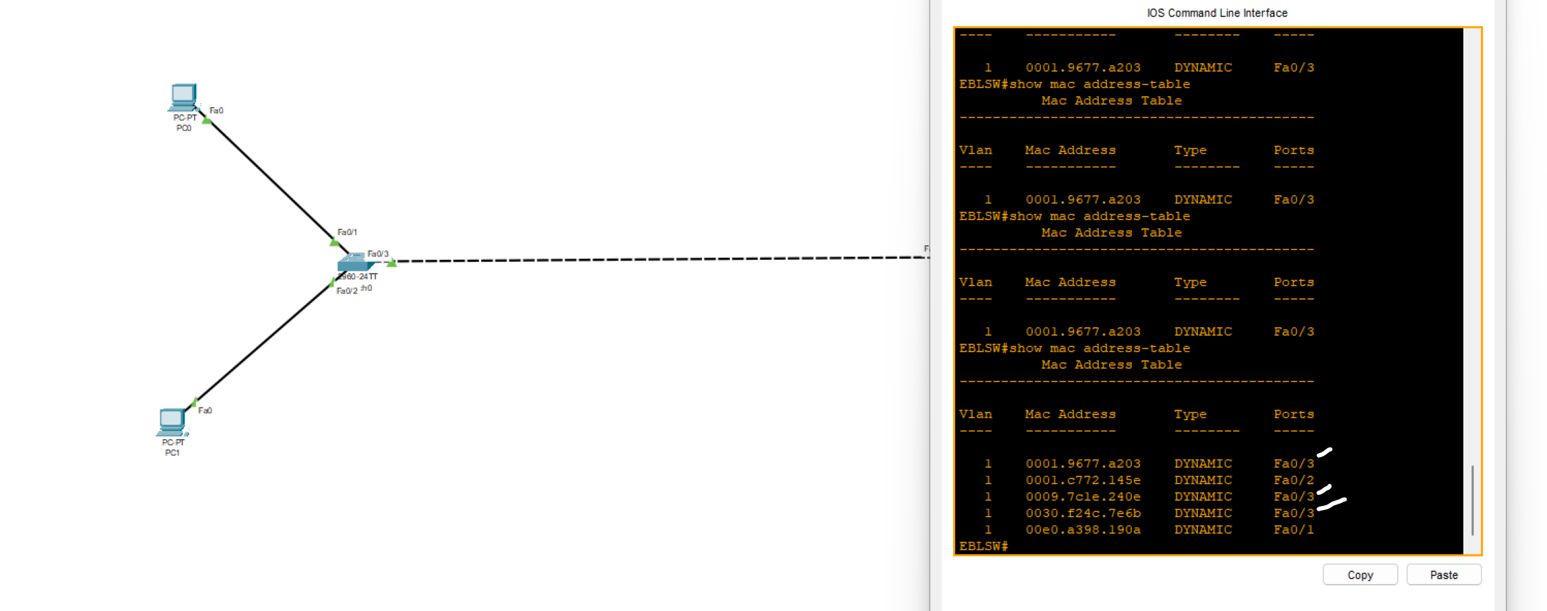
Why are there three MAC addresses showing through port FA0/3?
because the MAC addresses of other computers are received by the switch through port 0/3
- Use the command below on your switch device to see the MAC address age
EBLSW#show mac-address-table aging-time
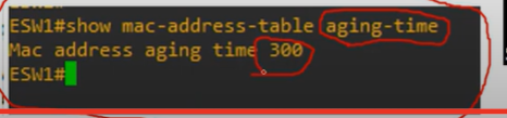
💡 After 300 seconds (5 minutes) of inactivity on the switch, it automatically resets the MAC address table.
- Use the commands below on your switch device to clean the MAC table
Switch#clear mac address-table dynamic
Additionally, we can delete a specific MAC address or interface from incoming frames.
Refer to the exhibit. Host A has sent a packet to host B. What will be the source MAC and IP addresses on the packet when it arrives at host B?
- Source MAC: 00E0.FE91.7799 Source IP: 10.1.1.10
What is CDP?
Cisco Discovery Protocol(CDP) is a network discovery tool that assists network administrators and engineers in identifying neighbouring Cisco devices. CDP is a layer 2 proprietary protocol that is default-enabled on all Cisco devices, including routers and switches.
EBLSW#show cdp neighbors
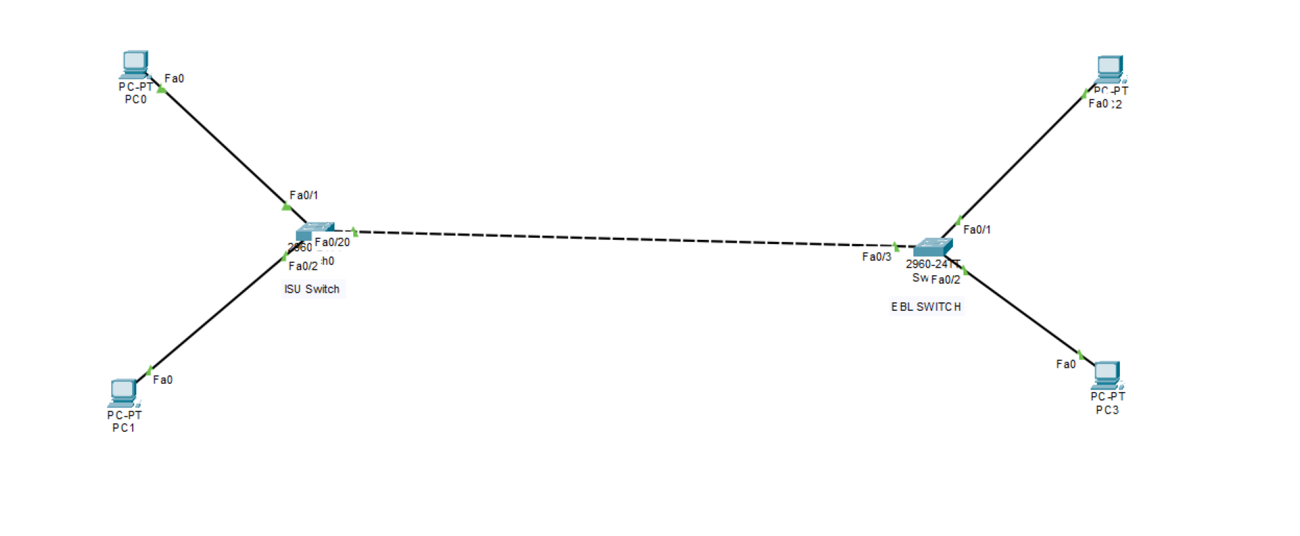
Capability Codes: R - Router, T - Trans Bridge, B - Source Route Bridge S - Switch, H - Host, I - IGMP, r - Repeater, P - Phone Device ID Local Intrfce Holdtme Capability Platform Port ID ISUSW Fas 0/3 149 S 2960 Fas 0/20
| (config)# cdp run | Enables CDP globally on device. |
| (config)# no cdp run | Disables CDP globally on device. |
| (config-if)# cdp enable | Enables CDP on an interface device if CDP isn’t enabled globally. |
| (config-if)# no cdp enable | Disables CDP on an interface device. |
| (config)# cdp timer <seconds> | Specifies CDP packets transmission frequency. Default 60 sec. |
| (config)# cdp holdtime <seconds> | Specifies time limit for which a receiving device should hold information before discarding. Default 180 sec |
| R1(config)# [no] cdp advertise-v2 | Enable/disable CDPv2 |
💡
cdp runEnable CDP globally on the device.
cdp enableEnable CDP on a specific interface.💡 Note: This protocol is exclusive to Cisco products only.
In a CDP environment, what happens when the CDP interface on an adjacent device is configured without an IP address?
- CDP operates normally, but it cannot provide IP address information for that neighbor
What is LLDP?
Link Layer Discovery Protocol (LLDP) is a layer 2 neighbour discovery protocol that allows devices to advertise device information to their directly connected peers/neighbours. It is best practice to enable LLDP globally to standardize network topology across all devices, especially in multi-vendor networks.
💡 ● LLDP is usually globally disabled by default.
● LLDP is also disabled on each interface by default.
| (config)# lldp run | Enables LLDP globally on device. |
| (config)# no lldp run | Disables LLDP globally on device. |
| (config-if)# lldp transmit | Enables LLDP on an interface device if LLDP isn’t enabled globally.(use together with receive) |
| (config-if)# lldp receive | Enables LLDP on an interface device if LLDP isn’t enabled globally. (use together with transmit) |
| (config)# lldp timer <seconds> | Specifies CDP packets transmission frequency. Default 30 seconds. |
| (config)# lldp holdtime <seconds> | Specifies time limit for which a receiving device should hold information before discarding. Default 120 seconds. |
| R1(config)# lldp reinit | this timer will delay the actual initialization of LLDP. 2 seconds by default. |
Local Interface: the physical port on your switch where the neighbor is connected.
Port ID: the neighbor’s interface identifier (how the neighbor advertises its port).
Refer to the exhibit. The network administrator must prevent the switch Cat9K-2 IP address from being visible in LLDP without disabling the protocol.
Which action must be taken must be taken to complete the task?
A. Configure the no lldp tlv-select-management-address command globally on Cat9K-2 B. Configure the no lldp transmit command on interface G1/0/21 in Cat9K-1 C. Configure the no lldp receive command on interface G1/0/21 on Cat9K-1 D. Configure the no lldp mac-phy-cfg command globally on Cat9K-2
💡 To hide Cat9K‑2’s IP without disabling LLDP, stop advertising the Management Address TLV on the device that’s sending it. On Cat9K‑2: no lldp tlv-select management-address
Introducing IP Addresses
What is an IP Address?
Internet protocol(IP)address: an identifying number that is associated with a specific computer or computer network. When connected to the internet, the IP address allows the computers to send and receive information.
IP Addresses are 32-bit numbers that are typically displayed in dotted decimal notation. A 32-bit address contains two primary parts: The network prefix and the host prefix.
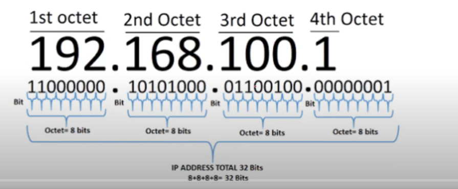
IP Address to Binary
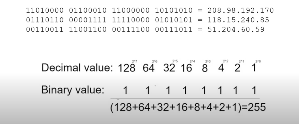
Note: 0-255 includes 256 IP addresses.
Characteristics of IP
- Connectionless: There is no connection with the destination established before sending data packets.
- Best Effort: IP is inherently unreliable because packet delivery is not guaranteed.
- Media Independent: Operation is independent of the medium (e.g., copper, fiber-optic, or wireless) carrying the data.
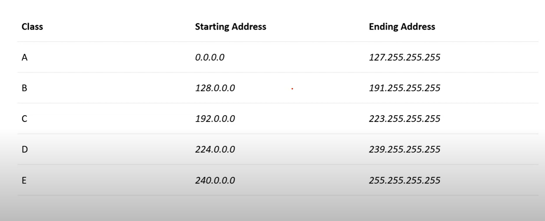
IP Addresses Classes
| Public IP Range | Private IP Range | Subnet Mask | # of Networks | # of Hosts per Network | ||
| Class A | 1.0.0.0 to127.0.0.0 | 10.0.0.0 to10.255.255.255 | 255.0.0.0 | 126 | 16,777,214 | |
| Class B | 128.0.0.0 to191.255.0.0 | 172.16.0.0 to172.31.255.255 | 255.255.0.0 | 16,382 | 65,534 | |
| Class C | 192.0.0.0 to223.255.255.0 | 192.168.0.0 to192.168.255.255 | 255.255.255.0 | 2,097,150 | 254 |
💡 The starting IP is called the Network address and is not usable.
The ending IP address is called the broadcast address, which is not usable.
The ending IP address is called the broadcast address, which is not usable.
Network Part
The network part of an IPv4 address is located on the left side. It identifies the specific network to which the address belongs and indicates the IP address class. This portion is crucial for routing and network identification.
For example, we have the IPv4 address 192.168.10.100 and a /24 subnet mask. /24 simply means that the first 24 bits, starting from the left side, are the network portion of the IPv4 address. The 8 remaining bits of the 32 bits will be the host portion.
Host Part
The host portion of the IPv4 address uniquely identifies the device or the interface on your network. Hosts that have the same network portion can communicate with one another directly, without the need for the traffic to be routed.
- Network Portion: Identifies the network to which the IP address belongs.
- Host Portion: Identifies the specific device within that network.
Class A
- 1.0.0.1 to 126.255.255.254(useable address).
- Support 16 million hosts on each of 126 networks.

Class A addresses are for networks with a large number of total hosts.
Class B
- 128.1.0.1 to 191.255.255.254
- Supports 65,000 hots on each of 16,000 networks.

If you use a class B, you can build more networks, but fewer hosts per network.
Class C
- 192.0.1.1 to 223.255.254.254
- Support 254 hosts on each of 2 million networks.

Class D
- 224.0.0.0 to 239.255.255.255.
- Reserved for multicast groups.
| Range Start Address | Range end Address | Description |
| 224.0.0.0 | 224.0.0.255 | Reserved for special “ well-know” multicast addresses. |
| 224.0.1.0 | 238.255.255.255 | Globally-scoped(internet-wide) multicast addresses |
| 239.0.0.0 | 239.255.255.255 | Administratively-scoped(local) multicast addresses |
When the IP Address Started from 224 to 239
Class E
- 240.0.0.0 to 254.255.255.254
- reserved for future use, or research and development purposes
- This IP class is reserved for experimental purposes only for R&D or study.
How to know the class of an IP address from binary?
- Class A: The first bit always has to be 0.
- Class B: The first 2 bits always have to be 10.
- Class C: The first 3 bits always have to be 110.
Subnet Mask
A subnet mask is a number that defines a range of IP addresses available within a network. A single subnet mask limits the number of Valid IPs for a specific network.
In this Image, three 255s are assigned to the network, and 0 octet is assigned to the host
Gateway
A gateway IP refers to a device on a network that routes local network traffic to other networks. The subnet mask defines the boundary between the network and host portions of an IP address, helping to determine which devices are on the same local network.
Public and Private IP addresses
- Public IP addresses are used on the Internet.
- Private IP addresses are used on your local area network and should not be used on the internet.
These are the Private IP address ranges:
- Class A: 10.0.0.0 – 10.255.255.255
- Class B: 172.16.0.0 – 172.31.255.255
- Class C: 192.168.0.0 – 192.168.255.255
Class A and B networks have a very large number of host addresses, and Class C has very few. Class A networks accounted for 50% of the IPv4 networks. This caused most of the available IPv4 addresses to go unused.
Loopback Address
A loopback address is a special IP address, 127.0.0.1, reserved by InterNIC for use in testing network cards, this IP address responds to the software loopback interface of the network card, which does not have hardware associated with it and does not require a physical connection to a network.
APIPA
Automatic Private IP Addressing(APIPA) is a feature in operating systems ( such as Windows) that enables computers to automatically self-configure an IP address and subnet mask when their DHCP server isn’t reachable. The IP Address range for APIPA is 169.254.0.1 to 169.254.255.254, with the subnet mask of 255.255.0.0
What are two features of IPv4 addresses? (Choose two.)
- IPv4 is a logical addressing scheme.
- An IPv4 addressing scheme is hierarchical.
Assignment of an IP address
Both IPv4 and IPv6 addresses are managed by the Internet Assigned Numbers Authority (IANA){ee·a·nuh}. The IANA manages and allocates blocks of IP addresses to the Regional Internet Registries (RIRs).
RIRs are responsible for allocating IP addresses to ISPs that provide IPv4 blocks to organizations and smaller ISPs.
Regional Internet Registries
Which organization or group of organizations receives IP addresses from IANA and is responsible for allocating these addresses to ISPs and some organizations?
RIRs
Refer to the exhibit. An administrator is troubleshooting connectivity on the office network. PC1 is able to send print jobs to Printer1, but is unable to access File Server1. Which action would correct the problem?
- Change the R1 Fa0/1 interface IP address to 10.231.64.1.
- Change the R1 Fa0/0 interface subnet mask to 255.255.0.0.
- Change the File Server1 IP address to 10.231.96.253.
- Change the PC1 IP address to 10.231.64.115.
Subnet ranges:
10.231.64.0 – 10.231.95.255→ Network B10.231.96.0 – 10.231.127.255→ Network A
IP Address Placement
- PC1:
10.231.92.115— in Network B (10.231.64.0/19) ✅ - Printer1:
10.231.95.252— also in Network B ✅ - File Server1:
10.231.127.253— in Network A ✅ - R1 Fa0/1:
10.231.128.1— ⚠️ This is the problem - Change the R1 Fa0/1 interface IP address to 10.231.64.1. (correct answer)
Network Segmentation (Basic of Subnetting)
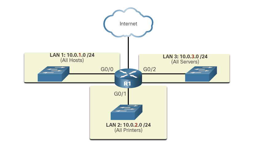
Broadcast Domain: is a collection of network devices that receive broadcast traffic from each other.
Subnetting is the practice of dividing a network into two or more smaller networks. It increases routing efficiency, enhances network security, and reduces the size of the broadcast domain**.**
Routers do not propagate broadcasts. When a router receives a broadcast, it does not forward it out other interfaces. For instance, when R1 receives a broadcast on its Gigabit Ethernet 0/0 interface, it does not forward it out another interface.
Therefore, each router interface connects to a broadcast domain, and broadcasts are only propagated within that specific broadcast domain.
Problems with Large Broadcast Domains
A large broadcast domain is a network that connects many hosts. A problem with a large broadcast domain is that these hosts can generate excessive broadcast traffic, which negatively affects the network.
LAN 1 connects 400 users, which could generate an excessive amount of broadcast traffic. This results in slow network operations due to the significant amount of traffic it can cause, and slow device operations because a device must accept and process each broadcast packet.
The solution is to reduce the size of the network to create smaller broadcast domains in a process called subnetting.
In the figure, the 400 users in LAN 1 with network address 172.16.0.0 /16 have been divided into two subnets of 200 users each: 172.16.0.0 /24 and 172.16.1.0 /24. Broadcasts are only propagated within the smaller broadcast domains. Therefore, a broadcast in LAN 1 would not propagate to LAN 2.
💡 Notice how prefix length has changed from a single /16 network to two /24 networks. This is the basics of subnetting
Reasons for Segmenting Networks
Subnetting reduces overall network traffic and improves network performance. It also enables network administrators to implement security policies such as which subnets are allowed or not allowed to communicate together. Another reason is that it reduces the number of devices affected by abnormal broadcast due to misconfiguration, hardware/software problems, or malicious intent.
Network Administrator can group devices and services into subnets
- Subnetting by Locations
- Subnetting by group or function
- Subnetting by device type
###
Which devices will not forward an IPv4 broadcast packet by default?
- router
Which two situations are the result of excessive broadcast traffic?
- slow device operations
- slow network operations
class A
10.0.0.0/8 (network prefix) meaning 8-bit located for the network ID portion and 24-bits for the host portion
10.0.0.0 255.0.0.0 (subnet mask) — equivalent to writing prefixes.
| Subnet mask (decimal) | 255 | 0 | 0 | 0 |
| Subnet mask (binary) | 11111111 | 00000000 | 00000000 | 00000000 |
class B
172.16.0.0/16 (network prefix) meaning 16 bits are located for the network ID portion and 16 bits for the host portion
172.16.0.0 255.255.0.0 (Subnet mask) equivalent to writing prefixes.
| Subnet mask (decimal) | 255 | 255 | 0 | 0 |
| Subnet mask (binary) | 11111111 | 11111111 | 00000000 | 00000000 |
192.168.1.0/24 (network prefix) meaning 24-bit located for the network ID portion and 8-bits for the host portion
192.168.1.0 255.255.255.0 (Subnet mask) equivalent to writing prefixes.
| Subnet mask (decimal) | 255 | 255 | 255 | 0 |
| Subnet mask (binary) | 11111111 | 11111111 | 11111111 | 00000000 |
Scenarios
Someone tells you to create three different networks for my organization or company
Class C
As you can see, we have created three networks in Class C. The third octet has been changed, and two routes have been added to route data from one network to another.
Note: if we don’t change the third octet, all devices are in the same network.
⚠️ This class includes 254 IP addresses for the host portion, unsuitable for large organizations.
Class B
Class A
Classless(CIDR)
- In the classful addressing method, millions of class A addresses are wasted.
- Many of the class B addresses are wasted.
- Class C is so small that it cannot cater to the needs of organizations.
- Classful networking was replaced by Classless Inter-Domain Routing(CIDR) in 1993
Subnetting
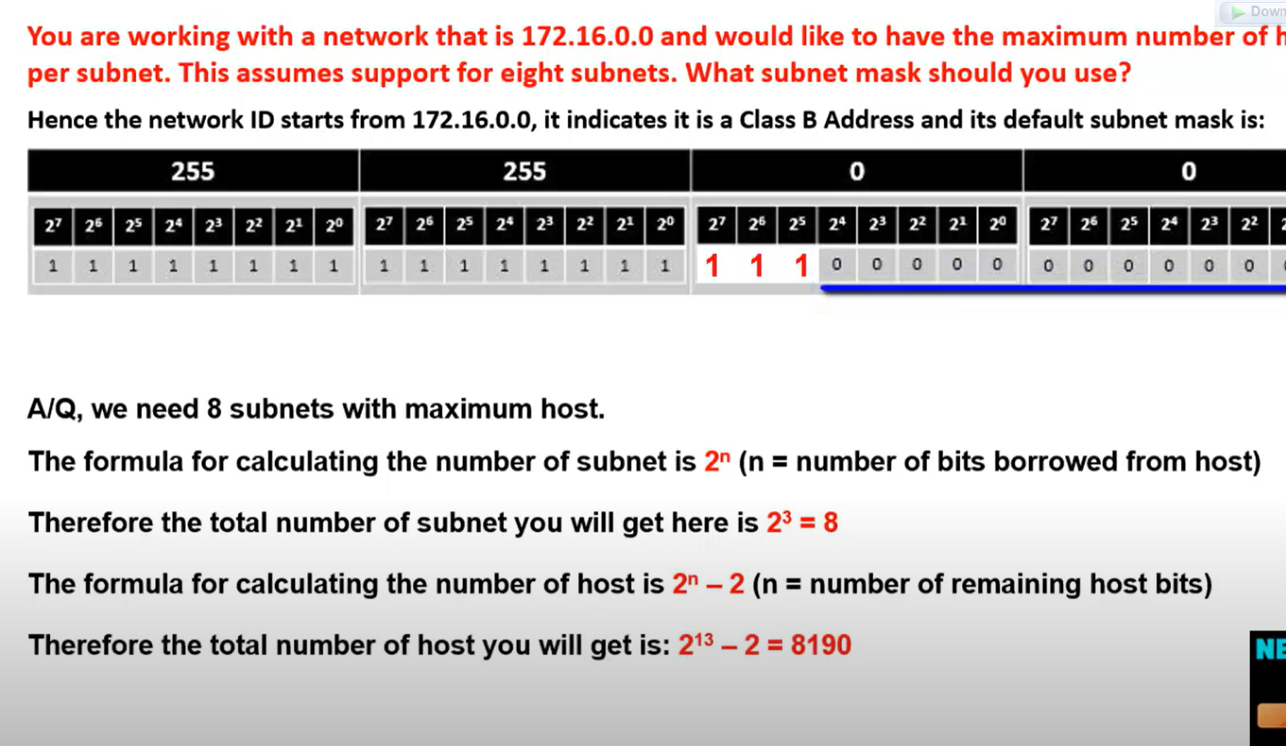
$2^n$=number of required network = total number of subnets
192.168.23.117/24 subnet this IP to 7 subnets
$2^n$=number of the required network
$2^n$(number of remaining bits for a host) - 2 = total hosts in the network.
| 128 | 64 | 32 | 16 | 8 | 4 | 2 | 1 |
| 2^7 | 2^6 | 2^5 | 2^4 | 2^3 | 2^2 | 2^1 | 2^0 |
2_^_3=8 any number but should be greater than 7
Now we borrow three bits from the host portion for the network portion.
| 128 | 64 | 32 | 16 | 8 | 4 | 2 | 1 |
| 1 | 1 | 1 | 0 | 0 | 0 | 0 | 0 |
128+64+32= 224 new subnet mask 255.255.255.224
The last 1 bit decides how the network is incremented.
In this example, our network incremented by 32 after minus 2 for the network ID and broadcast 14 active IPs for each subnet. 32-2=30
| Network.id | First valid host | Last Valid host | Broadcast.id |
| 192.168.23.0 | 192.168.0.1 | 192.168.23.30 | 192.168.23.31 |
| 192.168.23.32 | 192.168.0.33 | 192.168.23.62 | 192.168.23.63 |
| 192.168.23.64 | 192.168.0.65 | 192.168.23.94 | 192.168.23.95 |
| 192.168.23.96 | 192.168.0.97 | 192.168.23.126 | 192.168.23.127 |
| 192.168.23.128 | 192.168.0.129 | 192.168.23.158 | 192.168.23.159 |
| 192.168.23.160 | 192.168.0.161 | 192.168.23.190 | 192.168.23.191 |
| 192.168.23.192 | 192.168.0.193 | 192.168.23.222 | 192.168.23.223 |
💡 First, write all network IDs, then write broadcast IDs, and then write the first and the last host.
Network ID: T**he last octet is always an even number.**Broadcast ID: The last octet is always an odd number.
Network ID = incremented by the last bit value as I described.
Broadcast Id = Network ID before -1.
First valid host= Network.id+1.
Last Valid host id = broadcast.id -1
Network ID: T**he last octet is always an even number.**
Broadcast ID: The last octet is always an odd number.
Network ID = incremented by the last bit value as I described.
Broadcast Id = Network ID before -1.
First valid host= Network.id+1.
Last Valid host id = broadcast.id -1
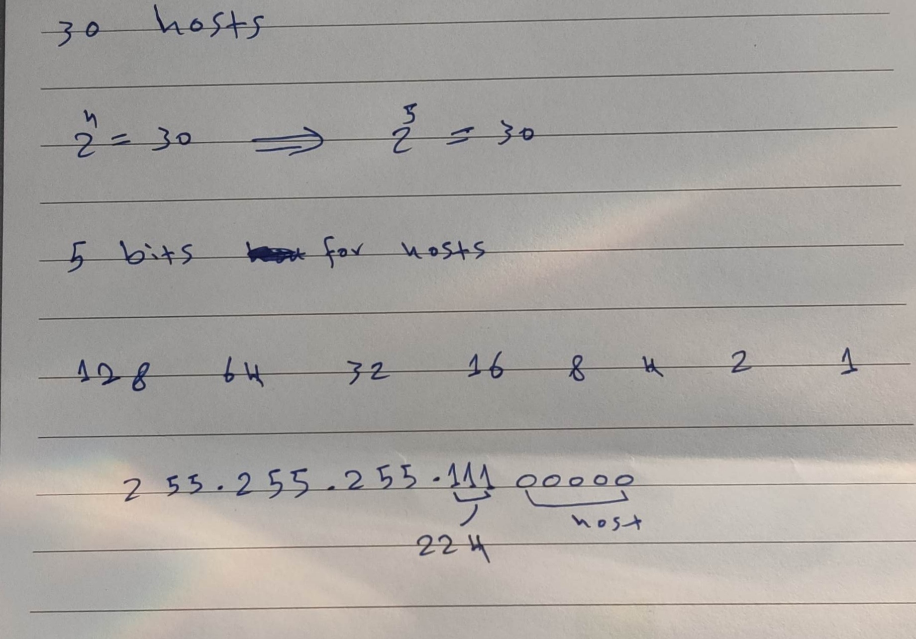
If you would like to give an IP address to 30 hosts from your IP prefix, which subnet mask do you use most effectively?
| A | 255.255.255.128 |
| B | 255.255.255.240 |
| C | 255.255.255.248 |
| D | 255.255.255.254 |
| E | 255.255.255.224 |
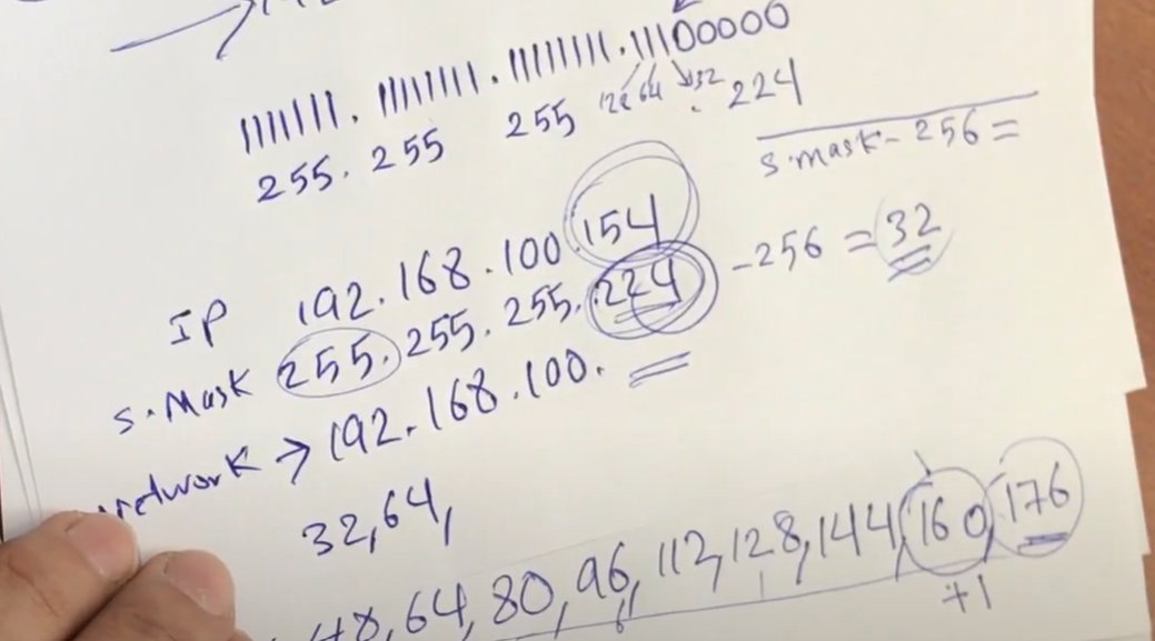
PC1's IP address is 10.89.107.233/27. What is the network address of its subnet?
## Here are a few super-fast ways:
Quick Formula
Block size= 256 − mask_octetNetwork= (⌊IP_octet ÷ block⌋ × block)Broadcast= Network + block − 1
Given:
IP =10.89.107.233/27Subnet mask/27→255.255.255.224Block size =256 − 224 = 32
Formula:
Network = (⌊octet ÷ block⌋ × block)
Focus on thelast octet(233).Divide: 233 ÷ 32 =7.28…Floor =7Multiply: 7 × 32 =224
Result:
Network address = 10.89.107.224/27 ✅
Broadcast Address
Broadcast = Network + block − 1
Broadcast = 224 + 32 = 256-1 = 255
Broadcast address = 10.89.107.255/27 ✅
Step 1: Understand the /27 Subnet Mask
- A /27 subnet means 27 bits for the network and 5 bits for the hosts.
- The subnet mask is:255.255.255.224
- 224 in the fourth octet = 11100000 in binary.
- The block size (increment) in the fourth octet is:
$256−224=32$
- This means subnets increase in steps of 32 in the fourth octet.
Step 2: Identify the Network Address
- The fourth octet of 10.89.107.233 is 233.
- Find the X*32 that is ≤ 233: (x32 smaller than 233) $732=224 ≤ 233$
- So, the network address is: 10.89.107.224/27.
Question 2: A host has the IP address 192.168.249.177/28. What is the broadcast address of its subnet?
Step 1: Understand the /28 Subnet Mask
- A /28 subnet means 28 bits for the network and 4 bits for hosts.
- The subnet mask is: 255.255.255.240
- The block size (increment) in the fourth octet is: $256−240=16$
- This means subnets increase in steps of 16 in the fourth octet.
Step 2: Find the Broadcast Address
- The fourth octet of 192.168.249.177 is 177.
- Find the X*16 that is ≥ 177 (x*16 greater than 177):
$12*16 =192 ≥ 177 $
- The broadcast address is one less than the next subnet:
- 192.168.249.192 - 1 = 192.168.249.191.
Easy way to find network ID (Subnet ID - network ID)
172.25.167.176
255.255.240.0
172.255. .0
3 rules applied to subnet mask
- If the subnet mask value=255 writes the same IP, for example, 255 above 172.
- If the subnet mask value=0, just set 0 zero instead of the IP.

3- 256- subnet mask = Network increment
We have three rules for Broadcast
- 255 → Ip
- 0 → 255
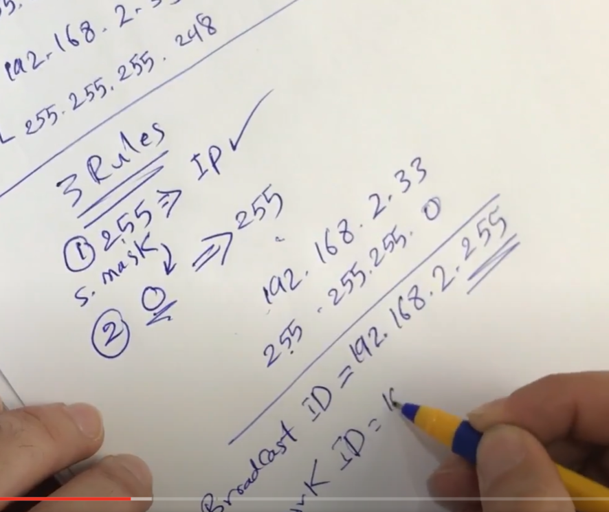
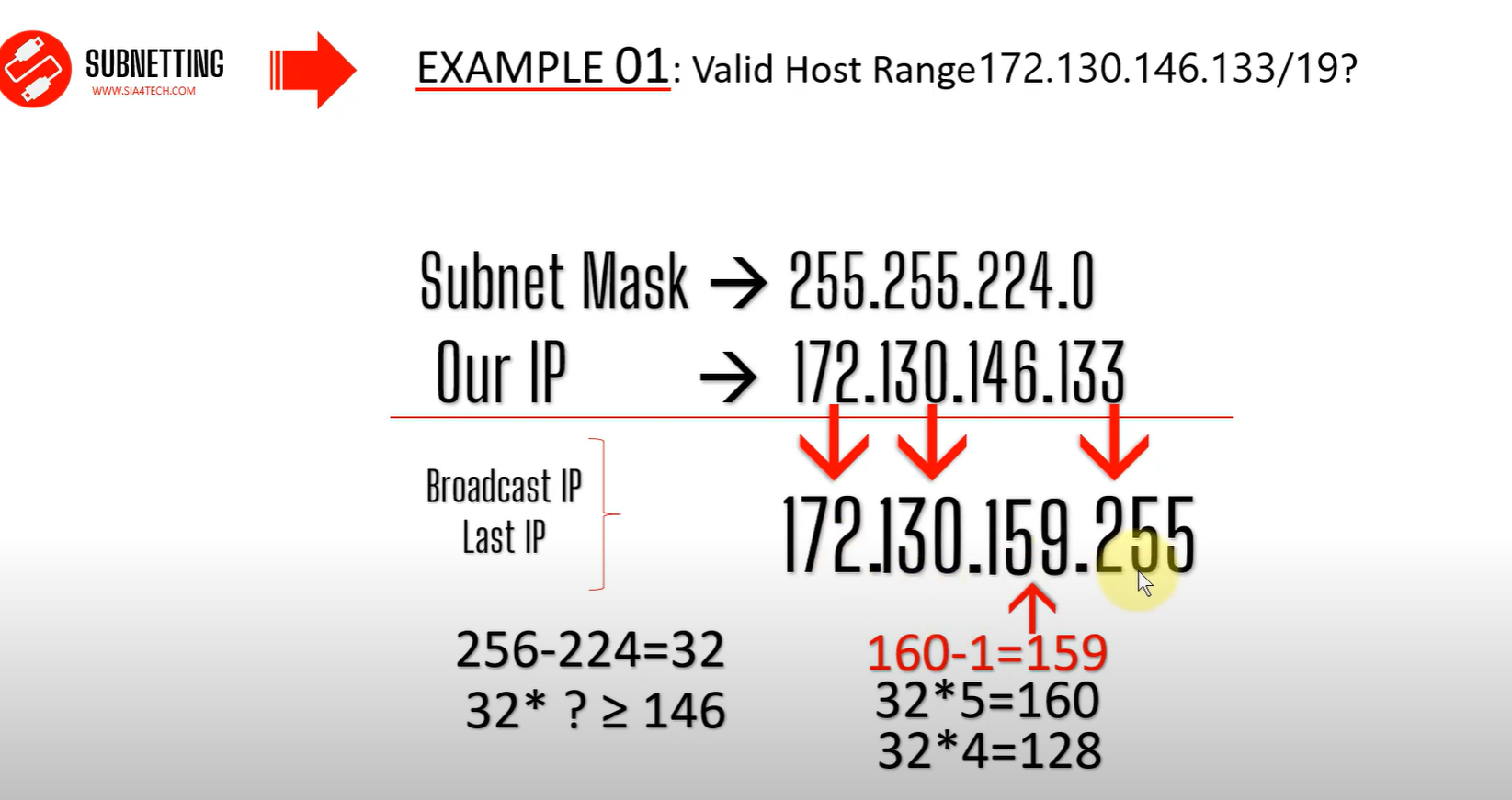
CCNA SUBNETTING: Find the Valid Host Range for a network
Find a valid Host range 172.130.146.133/19?
Now we need to find the Host ID and Broadcast ID
Network ID
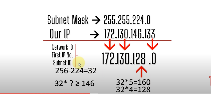
For the subnet mask, we chose a smaller number.
Broadcast ID
Differences between FLSM Subnetting and VLSM Subnetting
| FLSM (Fixed Length Subnet Masks) Subnetting | VLSM (Variable Length Subnet Masks) Subnetting |
| All subnets are equal in size. | Subnets are variable in size. |
| All subnets have equal number of hosts. | Subnets have variable number of hosts. |
| All subnets use same subnet mask. | Subnets use different subnet masks. |
| It is easy to configuration and administration. | It is complex in configuration and administration. |
| It wastes a lot of IP addresses. | It wastes minimum IP addresses. |
| It is also known as classfull Subnetting. | It is also known as classless Subnetting. |
| It supports both classfull and classless routing protocols like RIP-2 . | It supports only classless routing protocols like OSPF and EIGRP,. |
VLSM Subnetting
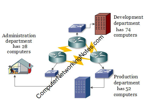
In this network: -
- The development department has 74 computers.
- The production department has 52 computers.
- The administration department has 28 computers.
- Departments are connected via the WAN links.
- Each WAN link requires two IP addresses.
- The given address space is 192.168.1.0/24.
VLSM
- Assign the largest at the start of the address space.
- Assign the second-largest subnet after it.
- Repeat the process until all subnets have been assigned.
Subnetting Question
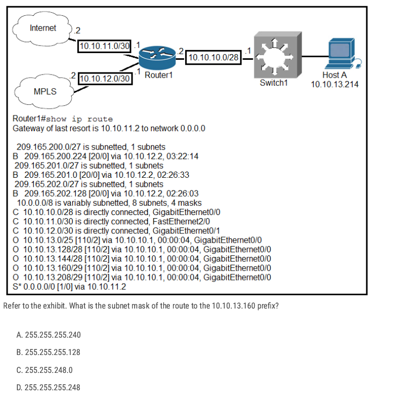
10.10.13.160/29 The subnet mask is 255.255.255.248 (block size 8). That subnet covers 10.10.13.160–10.10.13.167 with usable hosts .161–.166 and .167 as broadcast.
D ✅
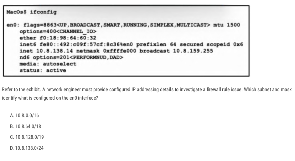
Netmask: 0xffffe000 → this hex mask equals 255.255.224.0, i.e. /19.
C ✅
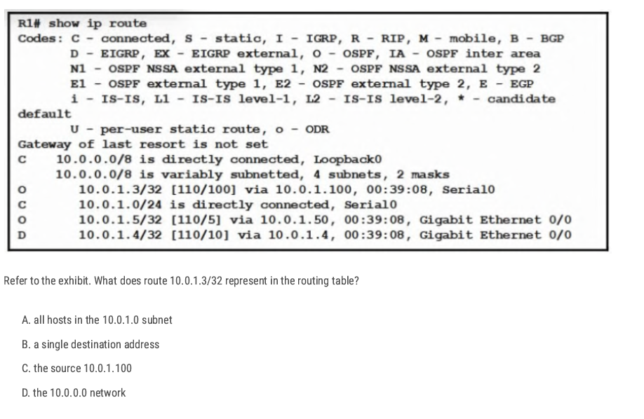
The prefix /32 (mask 255.255.255.255) is a host route—it matches exactly one IP address, here 10.0.1.3. So that entry represents a route to just that single host,
B✅
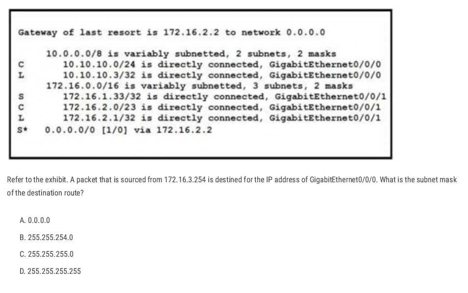
The destination is the IP of GigabitEthernet0/0/0, which the table shows as the local route:
L 10.10.10.3/32 is directly connected, GigabitEthernet0/0/0
Routing uses the longest prefix match. Between 10.10.10.0/24 and 10.10.10.3/32The/32 host route is more specific, so it’s the destination route. A /32 corresponds to the subnet mask 255.255.255.255.
D✅
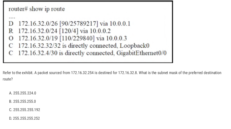
The destination IP is 172.16.32.8. From the routing table, the matching routes are:
172.16.32.0/26172.16.32.0/24172.16.32.0/19
the /26 network. By longest-prefix match, /26 is preferred over /24 and /19
C✅
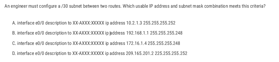
255.255.255.252 → mask is /30
10.2.1.3 255.255.255.252 → mask is /30 (correct), but .3 in a /30 is the broadcast of the block (.0–.3), so not usable.
D✅
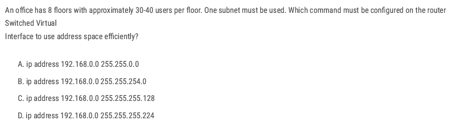
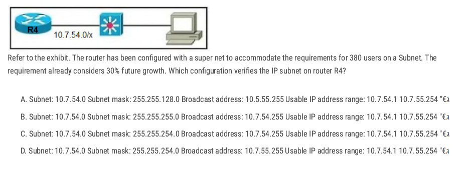
8 floors × 30–40 users = about 320 users total. All users must be in one subnet. Need a subnet that can support at least 320 usable hosts.
2^9 B✅
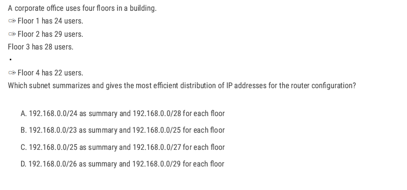
Each floor needs ≈ 22–29 hosts → choose /27 (255.255.255.224), which gives 30 usable IPs per floor.
Four /27 subnets (4 × 32 addresses) occupy 128 addresses total, which aggregates perfectly into a /25 block.
If you have 4 (subnet) × /27
- 4 (subnet)× 32 (block size) =128 addresses total
- That means the four /27 networks together span 128 consecutive addresses.
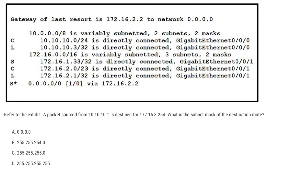
The packet is going to: 172.16.3.254
Which network covers 172.16.3.254?
- 172.16.1.33/32 → only 172.16.1.33, does not cover 172.16.3.254.
- 172.16.2.1/32 → only 172.16.2.1, does not cover 172.16.3.254.
- 172.16.2.0/23 → covers 172.16.2.0 – 172.16.3.255, and yes, 172.16.3.254 is inside this range.
B✅
D✅
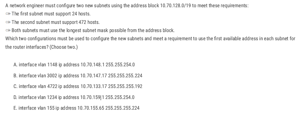
Group needing 24 hosts →/27 (255.255.255.224)
A and D → 255.255.254.0
- A: 10.70.148.1 /23 → network 10.70.148.0/23, and .1 is the first usable. ✅
- D misaligns a /23 (159 is odd; /23 networks start on even octets: …148.0, 150.0, 152.0, …, 158.0). ❌
Group needing 472 hosts → /23 (255.255.254.0)
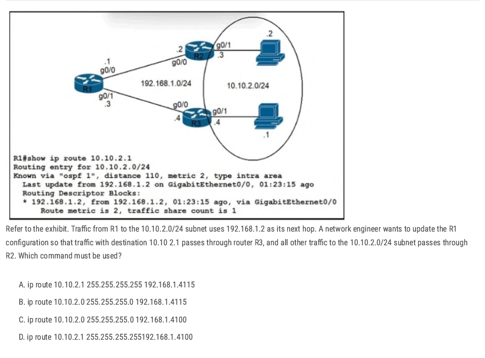
D. ip route 10.10.2.1 255.255.255.255 192.168.1.4 100
The administrative distance 100 keeps it preferred over OSPF (110) even if prefix lengths were equal (not needed here, but harmless).
- 10.10.13.0 → 255.255.255.128 ( /25 )
- 10.10.13.128 → 255.255.255.240 ( /28 )
- 10.10.13.160 → 255.255.255.248 ( /29 )
- 10.10.13.252 → 255.255.255.252 ( /30 )
IP V6
Intro to IPV6 Address
- 128-bit Addresses are written as 32 hexadecimal digits.
- Digits are arranged into 8 groups of four to improve readability.
- Groups are separated by colons.
Hex:2001:0718:1c01:0016:20d:56ff:fe77:52a3
Why was Hexadecimal used in IPv6?
to create a large amount of unique IP addresses
| IPv4 | IPv6 |
| Total IP addresses 4,294,967,296 | Total IP Addresses:(2^128) |
| 32-bit | 128-bit |
| Binary bits are separated by a dot (.) | Binary bits are separated by a colon(:) |
| Exmple:192.168.1.1 | Example:2001:0718:1c01:0016;020d:56ff:fe77:52a3 |
| Five different classes of IP address | No Classifications |
| IPV4 supports broadcast | IPv6 doesn’t support broadcast |
| 4 octets | 8 hextet |
Zero Suppression
- Zero compression can only be used to compress a single contiguous series of 16-bit blocks expressed in colon hexadecimal notation.
- Zero compression can only be used once in a given address.
Rules
- If we have equal or more than two groups of 0000 we can change it to:: (The double colon (::) can only be used once within an address, otherwise there would be more than one possible resulting address.) Here is an example of the incorrect use of the double colon: 2001:db8::abcd::1234.
- Change 0000 to 0 only.
- Leading zero can be removed. 01ab can be represented as 1ab 00ab can be represented as ab 0a**00 can be represented as a**00

Original:2041:000:140f:0000:0000:0000:875B:131B
short:2041:0000:140F::875B:131B
shorter:2041:0:140F::875B:131B
IPV6 Prefixes
- The prefix is the part of the address that indicates the bits that have fixed values or are the bits of the subnet prefix.
- Prefixes for IPv6 subnets are expressed in the same way as (CIDR) notation for IPv4.
- For example, 21DA:D3::/48 and 21DA:D3:0:2F3b::/64 are IPv6 address prefixes.
- A subnet mask is not used for IPv6; only the prefix length notation is supported.
| Type | Prefix | Scope | Purpose / Use | Example |
| Global Unicast | 2000::/3 | Global (Internet) | Public IPv6 address, routable on the Internet (like IPv4 public addresses). | 2001:db8::1 |
| Unique Local (ULA) | FC00::/7 (FDxx::) | Local (Private) | Works like private IPv4 (10.x.x.x, 192.168.x.x), used in internal networks. | FD12:3456:789A::1 |
| Link-Local | FE80::/10 | Link (single segment) | Automatically assigned to every interface, used for local comms (neighbor discovery, routing). | FE80::1 |
| Multicast | FF00::/8 | One-to-many | Packets delivered to multiple devices at once (routing protocols, discovery). | FF02::1 (all nodes), FF02::2 (all routers) |
| Anycast | (uses Unicast) | Nearest (routing-based) | Same address assigned to multiple devices → traffic goes to closest one. | Common for DNS servers |
| Loopback | ::1/128 | Host only | Used by a host to test itself (like IPv4 127.0.0.1). | ::1 |
| Unspecified | ::/128 | None | Represents “no address”, used as source before a device gets an IP. | :: |
| IPv4-mapped | ::FFFF/96 | Transition | Allows IPv6-only nodes to talk to IPv4 nodes. | ::FFFF:192.0.2.128 |
IPv6 Header
Simpler than IPv4:
- Fixed 40-byte header.
- no checksum → faster processing.
- Loopback IPv6 address: an IPv6 address used on a loopback interface. the IPv6 loopback address is 0:0:0:0:0:0:0:1 which can be notated as ::1/128.
- Unspecified address: an IPv6 unspecified address is 0:0:0:0:0:0:0:0, which can be notated as :::/128
Link-Local
- IPv6 link-local addresses are equivalent to IPv4 link-local addresses(169.254.0.0/16).
- IPv4 link-local addresses are known as automatic private IP addressing (APIPA) addresses for computers running the current Microsoft Windows operating system.
- A Link-local address is required for Neighbor Discovery(NDP) processes and is always automatically configured, even in the absence of all other unicast addresses.
Link-local(EUI-64)
- used only between nodes connected on the same local link.
- When an IPv6 stack is enabled on a node, one link-local address is automatically assigned to each interface of the node at boot time.
- IPv6 link-local prefix FE80::/10 is used, and the interface identifier in Extended Unique Identifier 64 (EUI-65) format is appended as the address's low-order 64-bit.
- Link-local addresses are only for link-local scope and must never be routed between subnets within a site.
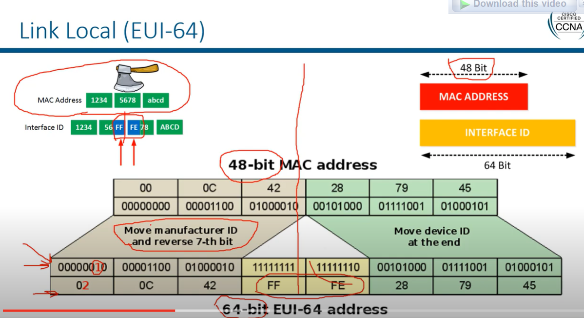
There's a challenge with creating the second 64 bits from the MAC address, as MAC addresses are only 48 bits long. To solve this, we insert FFFE in the middle of the MAC address.
Example Calculation:
- MAC Address:
AA:BB:CC:DD:EE:FF - Split the MAC Address:
AA:BB:CC|DD:EE:FF - Insert FFFE:
AA:BB:CC:FF:FE:DD:EE:FF - Flip the 7th Bit in AA (10101010 → 10101000):
A8:BB:CC:FF:FE:DD:EE:FF - Final EUI-64 Interface ID:
A8BB:CCFF:FEDD:EEFF
Router 2 (config)# interface FastEthernet0/0
Router 2 (config-if)# ipv6 enable
Router 2 (config-if)# ipv6 address autoconfig
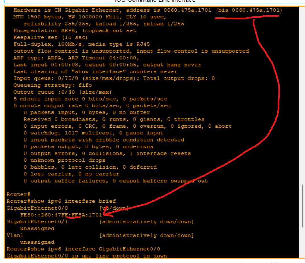
Loopback address
- The loopback address(0:0:0:0:0:0:0:1 or ::1) is used to identify a loopback interface, enabling the node to send a packet to itself.
- It is equivalent to the IPv4 loopback address of 127.0.0.1.
- Packets addressed to the loopback address must never be sent on a link or forwarded by an IPv6.
Broadcast
• Broadcast - There are no broadcast addresses in IPv6. Broadcast functionality is implemented using multicast addresses.
Anycast (not very important)
- An Anycast is an address that is assigned to a set of interfaces that typically belong to different nodes. A packet sent to an anycast address is delivered to the closest interface identified by the anycast address.
- Assigning a unicast address to more than one interface makes a unicast address an anycast address.
- Anycast is a network addressing and routing methodology in which datagrams from a single sender are routed to the topologically nearest node in a group of potential receivers, though it may be sent to several nodes, all identified by the same destination address. Example: Used in DNS query.
IPv6 Transaction
- Dual-stack: means a device runs both IPv4 and IPv6 at the same time. This allows networks to support both protocols during the transition from IPv4 to IPv6.
In a dual-stack environment, which protocol does a device prefer if both IPv4 and IPv6 are available?
- IPv6 is preferred if available
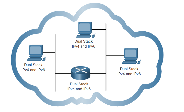
- Tunneling is a method of transporting an IPv6 packet over an IPv4 network. The IPv6 packet is encapsulated inside an IPv4 packet, similar to other types of data.
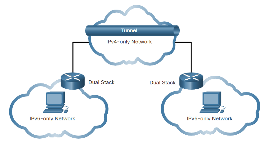
- Translation: Network Address Translation 64 (NAT64) allows IPv6-enabled devices to communicate with IPv4-enabled devices using a translation technique similar to NAT for IPv4. An IPv6 packet is translated to an IPv4 packet, and an IPv4 packet is translated to an IPv6 packet.
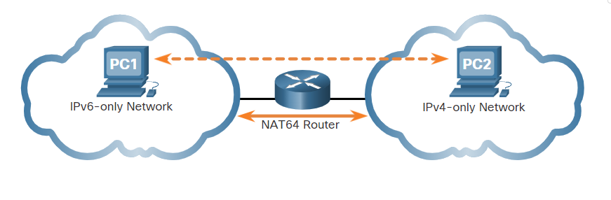
What is the most important motivating factor for moving to IPv6?
- Depletion of IPv4 addresses.
What is the default route address of IPv6?
- ::/0
Which field in an IPv6 packet is used by the router to determine if a packet has expired and should be dropped?
• Hop Limit
What is the prefix for the host address 2001:DB8:BC15:A:12AB::1/64?
- 2001:DB8:BC15:A
SLAAC (Stateless Address Auto Config):
a method used in IPv6 networks that allows devices to automatically configure their IPv6 addresses without the need for a DHCP server
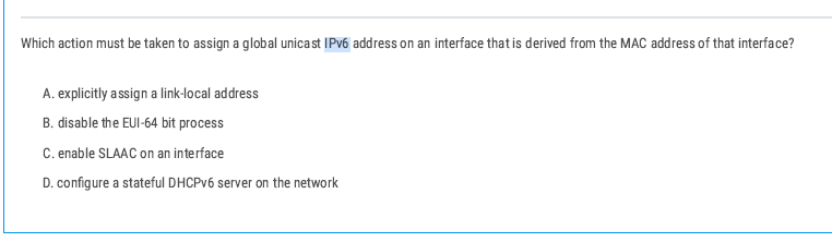
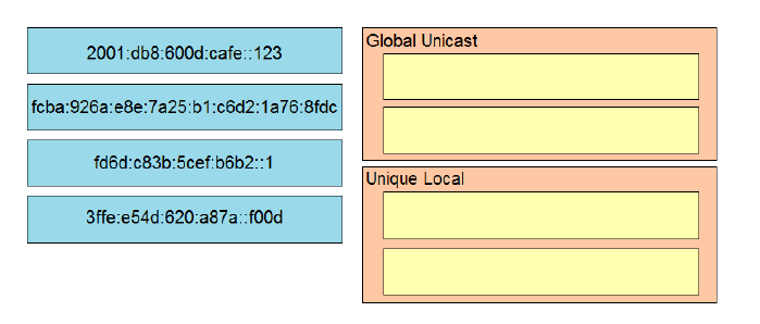
3ffe:e54d:620a:a87a:f00d is a Global Unicast Address because it starts with 3 , which is part of the 2000::/3 range for globally routable addresses.
An Anycast Address is similar to a unicast address because it is assigned to multiple devices, but traffic sent to this address is delivered to the closest (nearest) device in the group
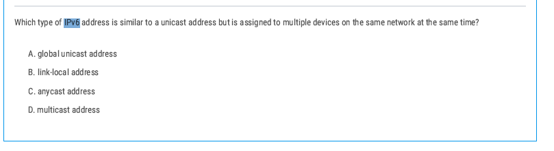
Anycast Address is similar to a unicast address because it is assigned to multiple devices, but traffic sent to this address is delivered to the closest (nearest) device in the group
The correct prefix length for the IPv6 address would be /128 because it refers to one specific host (the router interface).
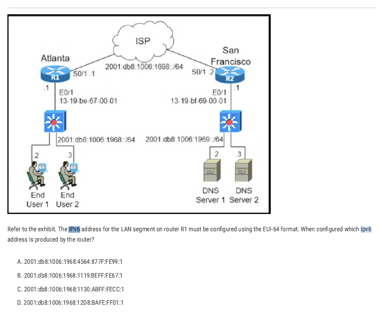
Take the MAC of R1’s LAN interface (E0/1 in the figure):
13-19-be-67-00-01 → in hex bytes: 13:19:be:67:00:01.
Split and insert ff:fe
in the middle (that’s how EUI-64 expands 48-bit MAC to 64-bit):
13:19:be + ff:fe + 67:00:01 → 13:19:be:ff:fe:67:00:01.
Flip the U/L bit (the 7th bit) of the first byte:
Resulting interface ID bytes: 11:19:be:ff:fe:67:00:01.
Group into hextets (two bytes each):
1119:beff:fe67:0001 → 1119:beff:fe67:1.
Attach the /64 prefix for R1’s LAN shown in the diagram:
Prefix = 2001:db8:1006:1968::/64.
Final IPv6 address: 2001:db8:1006:1968:1119:BEFF:FE67:1 → option B.
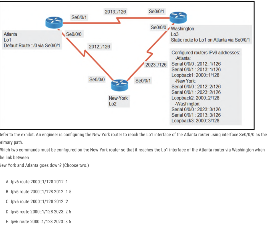
A. ipv6 route 2000::1/128 2012::1
[route loopback through next router IP 2012::1 IP addresses of Se0/0/0 interface]
E. ipv6 route 2000::1/128 2023::3 5
This is a floating static backup via Washington (Washington S0/0/0 = 2023::3) with a higher administrative distance (5).
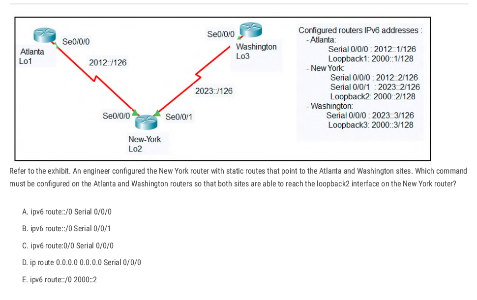
💡 ipv6 route ::/0 next-hop IPv6 or existing interface.
Answer: A On those two routers, the interface that faces New-York is Serial 0/0/0
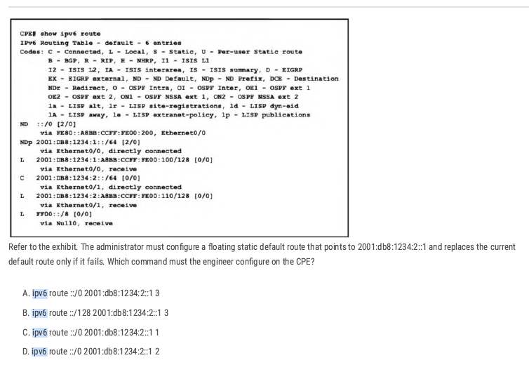
The current default route is ND and the syntax [X/Y] shows the administrative distance (X) and the metric (Y). Therefore, the primary default route, learned via Neighbor Discovery (ND), has an administrative distance of 2.
ipv6 route ::/0 2001:db8:1234:2::1 3 Correct [Higher AD for the Backup Route]
Correct: B. 2001:db8:0234:cae3::1/128
- Anycast in IPv6 uses global unicast addresses (/128) that are configured on multiple devices.
VLAN
Collision Domain
A collision domain is a network segment where devices share the same communication medium, and if two devices transmit data at the same time, their signals can collide, causing the transmission to fail and requiring retransmission. It happens only in half-duplex mode.
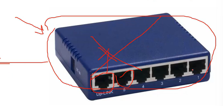
For example, a hub is one collision domain. If one port stops working, all ports stop working.
Broadcast Domain
When a device sends out a broadcast message, all devices present in its broadcast domain must pay attention to it. This creates a lot of congestion in the network, commonly referred to as LAN congestion, which affects the bandwidth available to users within that network.
In a switch, each port has a collision domain, without affecting other ports. When one port receives data, it broadcasts it to all other ports (which means broadcasting a message to all ports and telling them I have received a packet, for which of you?), then, network engineers decided to separate switches into small parts by using VLANs.
- One broadcast domain for the whole network or only the user network can lead to unnecessary broadcast traffic, which, upon a traffic loop, might cause a complete service outage.
- Secondly, but even more important, large broadcast domains are vulnerable to traffic sniffing and easier man-in-the-middle kind of attacks.
- A lack of VLANs can cause an administrative mess.
| Feature | Collision Domain | Broadcast Domain |
| Definition | A network segment where collisions can occur | A network segment where broadcasts are forwarded |
| Devices involved | Hubs, repeaters, old shared Ethernet networks | Switches (unless VLANs are used), all devices in a VLAN |
| Effect on traffic | Causes retransmissions due to collisions | Causes network congestion due to excessive broadcasts |
| Separation method | Switches (each port is a separate collision domain) | Routers or VLANs |
| Example devices | Hub-based networks | Switch-based networks without VLANs |
PC1 --- Hub --- PC2 --- Switch --- PC3
- Hub side (PC1 + PC2) = 1 collision domain.
- Switch separates PC3 into its own collision domain.
- So total = 2 collision domains.
💡 - Switch increases collision domains (per port).
- Hub shares 1 collision domain for all.
- Switch increases collision domains (per port).
- Hub shares 1 collision domain for all.
VLAN
VLANs(Virtual LANs) are a logical grouping of devices in the same broadcast domain. VLANs are usually configured on switches by placing some interfaces into one broadcast domain and some interfaces into another. Each VLAN acts as a subgroup of the switch ports in an Ethernet LAN.
Note: All nodes from VLAN one can’t access the nodes in VLAN two.
Note: VLAN one (VLAN 1) is allocated for the default VLAN(native VLAN).
| Range | Description |
| VLAN 1: | This is a default VLAN of switches. You cannot delete or edit this VLAN, but it can be used. |
| VLAN 2-4094: | It is a normal VLAN range. You can create, edit, and delete it. |
Advantages of using VLAN
- It solves a broadcast problem. By reducing the size of broadcast domains and increasing the number of Broadcast domains. (the primary advantage of using VLAN)
- VLAN allows you to add an additional layer of security.
- It can make device management simple and easier.
- VLAN makes managing physical devices less complex.
- It lets you easily segment your network.
- Make a single switch into multiple switches.
Native VLAN
The native VLAN is a special VLAN designated on a trunk port for carrying untagged traffic.
When a switch port is set as a trunk, any incoming Ethernet frame without a VLAN tag is assigned to the native VLAN.
💡 VLAN Hopping Attacks: By default, using VLAN 1 as the native VLAN can pose a security risk. A best practice is to configure the native VLAN as an unused or less critical VLAN to prevent potential VLAN hopping attacks.
Which VLANs exist by default on a Cisco switch and cannot be deleted?
- 1, 1002-1005
# Tagged VLANs
Tagged VLANs are a method of marking Ethernet frames with a VLAN identifier so that switches and network devices can distinguish between traffic from different VLANs on the same physical link. distinguish between traffic from different
The tagging standard used is IEEE 802.1Q.
When traffic is sent over a trunk port, each frame includes a VLAN tag (a 4-byte field added to the Ethernet frame header). This tag contains the VLAN ID, which specifies which VLAN the frame belongs to.
Trunk ports = Tagged ports
Access port = Untagged Ports
VLAN Configuration
SW1#show vlan
SW1(config)#vlan 10 (a number you assigned to the vlan)
SW1(config-vlan)# name sales (your vlan name)
SW1(config-vlan)#exit

SW1(config)# int fa0/3 (switch port that connected to the computer)
SW1(config)#switchport mode access(it means the port is not available on vlan1 and gets out from public accessing (valn1) and should be accessed by a VLAN I will assign to it.)
SW1(config)#switchport access vlan 10 ( your vlan number)
SW1(config)#end
Note: if you have multiple switches, the same configuration should be applied to all of them.
VLAN 3 is not yet configured on your switch. What happens if you set the switchport access VLAN 3 command interface configuration mode?
The command is accepted, and the respective VLAN is added to vlan.dat.
How do you see all VLANs created and ports assigned to the specific VLAN?
SW1#show vlan
Remove a Port From a VLAN (SEFOS)
switch(config)# interface gigabitethernet 0/2
switch(config-if)#no switchport access vlan [number]
switch(config-if)#exit
How to remove VLANs
SW1(config)#no vlan 10(vlan number you want to delete it).
Trunk
A trunk is a network link that carries multiple VLANs between devices, such as between switches, routers, or other network devices. It allows the transmission of traffic for more than one VLAN over a single physical link, reducing the number of physical connections required.
Encapsulation Types
802.1 IEEE can be used on all vendor devices.
ISL →previously used by Cisco, not usable today.
- Access Port: A port that can be assigned to a single VLAN. This type of interface is configured on switch ports that are connected to end devices, such as workstations or printers.
Trunk Port: A port that is connected to another switch. This type of interface can carry traffic of multiple VLANs.
Swith1(config)#interface fa0/0
Swith1(config-if)switchport mode trunk
Swith1(config-if)#switchport trunk allowed vlan (Vlan ID or range).
Swith1(config-if)#swithport nonegotiaite
Dynamic Trunking Protocol
- Dynamic Trunking Protocol is a Cisco proprietary protocol used for negotiating a trunk link between two switches, as well as the encapsulation type. It is a layer 2 protocol and is enabled by default.
- Switchport mode dynamic auto: This is a default mode on the older CISCO switches. This mode makes the interface able to convert to a trunk link. The interface will become a trunk link if the neighboring interface is set to trunk or desirable mode. If both switches’ interface mode is auto, then the trunk will not be formed.
- Switchport mode dynamic desirable: the interface will actively attempt to convert the link into a trunk link. The interface will become a trunk link port if the neighbouring interface is set to trunk. desirable or auto.
- Switchport nonegotiate (very usable technique): This mode prevents the interface from generating DTP frames. This command is used only when the switch port mode is accessed or turned on. You must manually configure the neighboring interface as a trunk interface to establish a trunk link.
Router on a stick (one-armed router)
A router on a stick is one method for allowing routing between VLANs. That kind of setup consists of a router and a switch connected through one Ethernet link configured as an 802.1q trunk link. Such a configuration is typical in networks where no layer-3 switch exists.
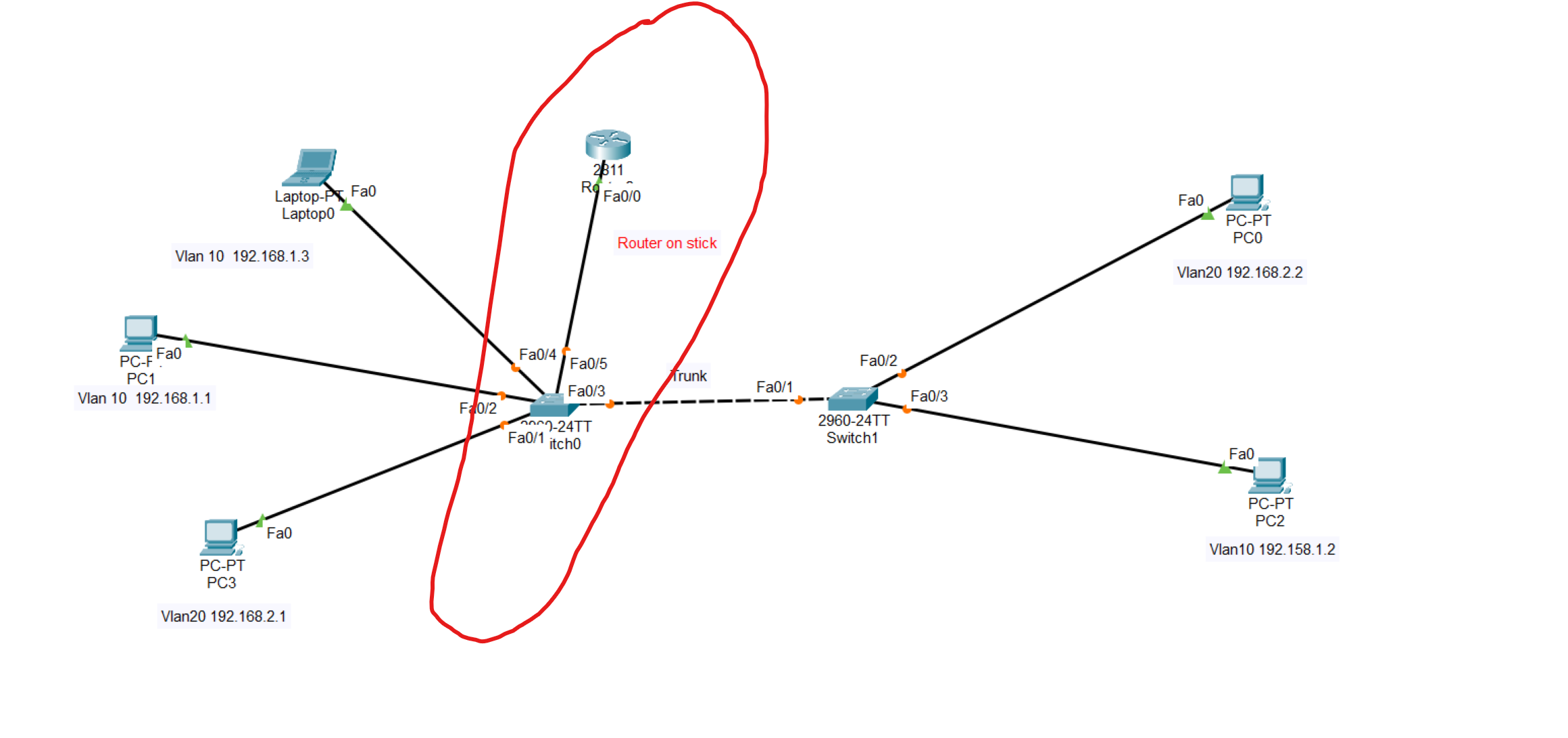
Router(config-if)# int fa0/0.10 (we should create 2 sub interfaces to each VLAN)
Router(config-subif)#encapuslation dot1q 10 (VLAN ID)
Router(config-subif)#ip address 192.168.1.55 255.255.255.0 (Assign an IP address from vlan 10 to the sub-interface)
------------second sub-interface -------------
Router(config-if)# int fa0/0.20
Router(config-subif)#encapuslation dot1q 10
Router(config-subif)#ip address 192.168.2.55 255.255.255.0
Use the same command to create a sub-interface to the second VLAN, then write the command no shutdown
💡 The subinterface number does not have to match the VLAN Number. However, it is highly recommended that they do match, to make it easier to understand.
💡 The gateway of all devices in VLAN 10 should be the IP address assigned to the sub-interface.
💡 The switch port connected to the router in the switch should be changed to a trunk.
VLAN Troubleshooting Commands
| show vlan show vlan brief | Lists each VLAN and all interfaces assigned to that VLAN (but does not include operational trunks) | | ----------------------------------------------------------------- | ---------------------------------------------------------------------------------------------------------------------------------------------------- | | show vlan id num | Lists both access and trunk ports in the VLAN | | show interfaces switchport show interfaces type number switchport | Identifies the interface’s access VLAN and voice VLAN, the configured and operational mode (access or trunk), and the state of the port (up or down) | | show interface status | Summarizes the status listing for all interfaces (connected, notconnect, err-disabled), the VLAN, duplex, speed, and type of port |
Which interfaces are shown in the output of "show vlan brief"?
- Access Ports
Trunking Troubleshooting
Step 1: Identify all access interfaces and their assigned access VLANs, and reassign them into the correct VLANs, as needed.
Step 2: Determine whether the VLANs exist and are active on each switch. If needed, configure and activate the VLANs to resolve problems.
Step 3: Check the allowed VLAN lists on the switches on both ends of the trunk and ensure that the lists of allowed VLANs are the same.
Step 4: Ensure that, for any links that should use trunking, one switch does not think it is trunking, while the other switch does not think it is trunking.
VLAN Trunking Protocol(VTP)
- The purpose of VTP is to provide a way to manage Cisco switches as a single group for VLAN configuration purposes. For example, if VTP is enabled on Cisco switches, the creation of a new VLAN on one switch makes that VLAN available to all switches within the same VTP management domain**.** A switch can be part of only one VTP management domain at a time, and is part of no VTP management domain by default.
To show VTP details
Router#show vtp status
VTP Operating Type: type of VTP.
How to set the VTP domain
Router(config)#vtp domain your-domain-name
VTP Operating Type:
Server: Receives and sends configuration from neighbouring switches.
Client: We only receive VLANs from the server switch and can’t create any VLAN with this mode.
Transparent: does not synchronize VLAN configuration information with other switches.
Router(config)#vtp mode your-mode
C. configure ports in a black hole VLAN
Because assigning unused ports to a blackhole VLAN ensures they are isolated, secure, and cannot be exploited if someone plugs into them.
- C → isolate unused ports in a dedicated, unused VLAN (blackhole VLAN).
- D → shut them down so no traffic pass
B and C
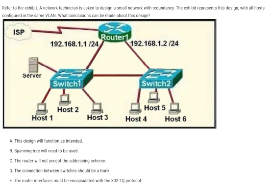
Answer: C — The router will not accept the addressing scheme.
In the diagram, Router1 has two physical interfaces in the same IP subnet (192.168.1.0/24). Cisco IOS does not allow assigning the same subnet to two different routed interfaces
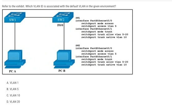
Answer: A — VLAN 1 (On Cisco switches, the default VLAN is always VLAN 1)
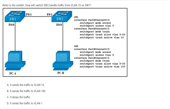
B. It sends the traffic to VLAN 100. Frames in the native VLAN are sent untagged on an 802.1Q trunk.
Correct Answer: B (When a PC sends untagged traffic to the IP phone, the phone simply forwards it unchanged (still untagged) toward the switch.)
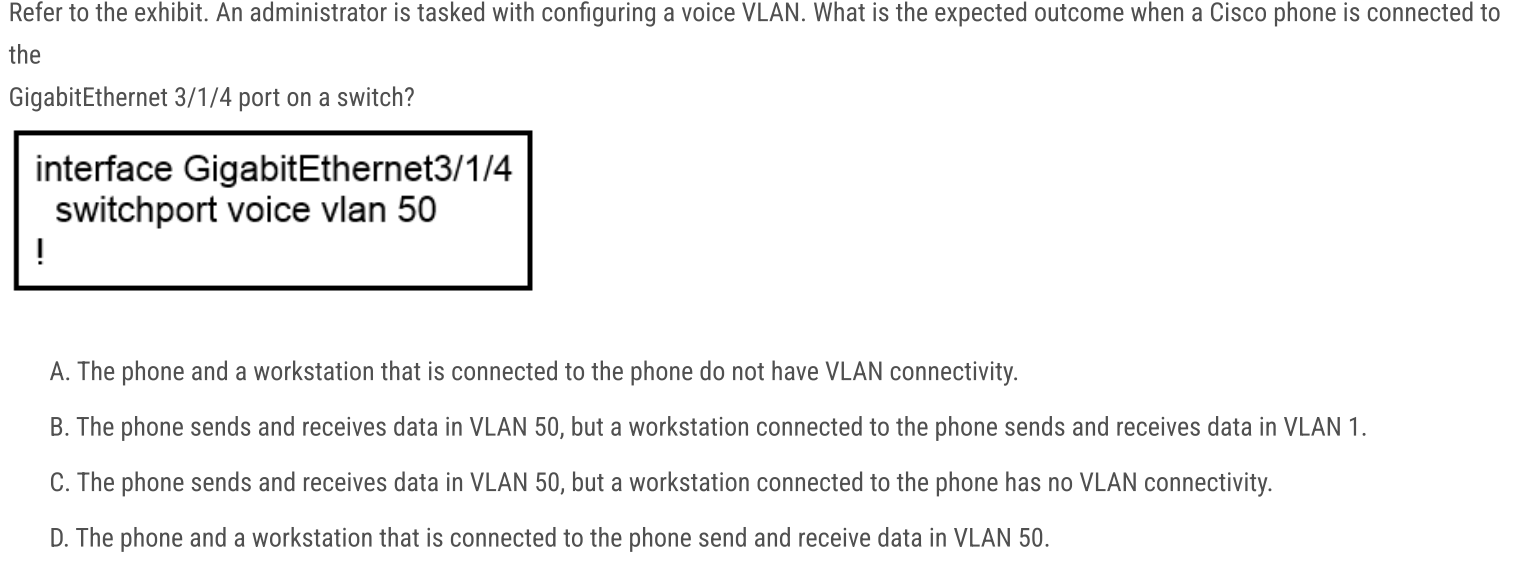
B. The phone uses VLAN 50, while the attached PC uses VLAN 1.
switchport voice vlan 50 tells the switch to expect tagged voice traffic from the Cisco IP phone on VLAN 50. PC traffic arriving via the phone is untagged and is placed into the port’s access VLAN—which, since none is configured, defaults to VLAN 1
C and E
A and C
VLAN Lab
In this scenario, we will configure VLANs on switches across multiple locations. We'll use trunking to allow devices in the same VLAN to connect, even when they're in different locations. Also providing routing between VLAN 10 and VLAN 30 through the Router on Stick technique.
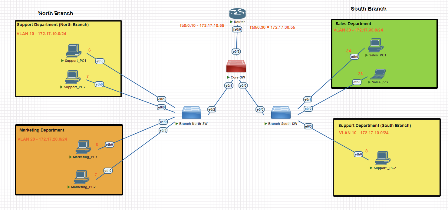
North Branch Switch
Creating VLAN 10
Branch-SW#conf t
Branch-SW(config)#vlan 10
Branch-SW(config-vlan)#name support
Branch-SW(config-vlan)#exit
Branch-SW(config)#interface range e0/0-1
Branch-SW(config-if-range)#switchport mode access
Branch-SW(config-if-range)#switchport access vlan 10
Creating VLAN 20
Branch-SW#conf t
Branch-SW(config)#vlan 20
Branch-SW(config-vlan)#name marketing
Branch-SW(config-vlan)#exit
Branch-SW(config)#int e 1/0
Branch-SW(config-if)#switchport mode  access
Branch-SW(config-if)#switchport access vlan 20
Branch-SW(config-if)#exit
Branch-SW(config)#int e0/3
Branch-SW(config-if)#switchport mode access
Branch-SW(config-if)#switchport access vlan 20
Branch-SW(config-if)#exit
Verifying Created VLANs
Branch-SW#show vlan brief
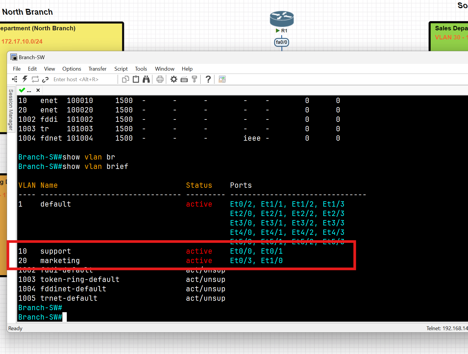
South Branch Switch
Creating VLAN 30
Branch-SW#conf t
Branch-SW-South(config)#vlan 30
Branch-SW-South(config-vlan)#name sales
Branch-SW-South(config-vlan)#exit
Branch-SW-South(config)#int range e0/1-2
Branch-SW-South(config-if-range)#switchport mode access
Branch-SW-South(config-if-range)#switchport access vlan 30
Branch-SW-South#wr
Creating VLAN 10
Branch-SW#conf t
Branch-SW-South(config)#vlan 10
Branch-SW-South(config-vlan)#name support
Branch-SW-South(config)#vlan 99 //this vlan for native vlan, we use it in the trunking step
Branch-SW-South(config-vlan)#name managment //this vlan for native vlan
Branch-SW-South(config-vlan)#exit
Branch-SW-South(config)#int e0/3
Branch-SW-South(config-if-range)#switchport mode access
Branch-SW-South(config-if)#switchport access vlan 10
Branch-SW-South#wr
Verifying Created VLANs
Branch-SW-South#show vlan brief
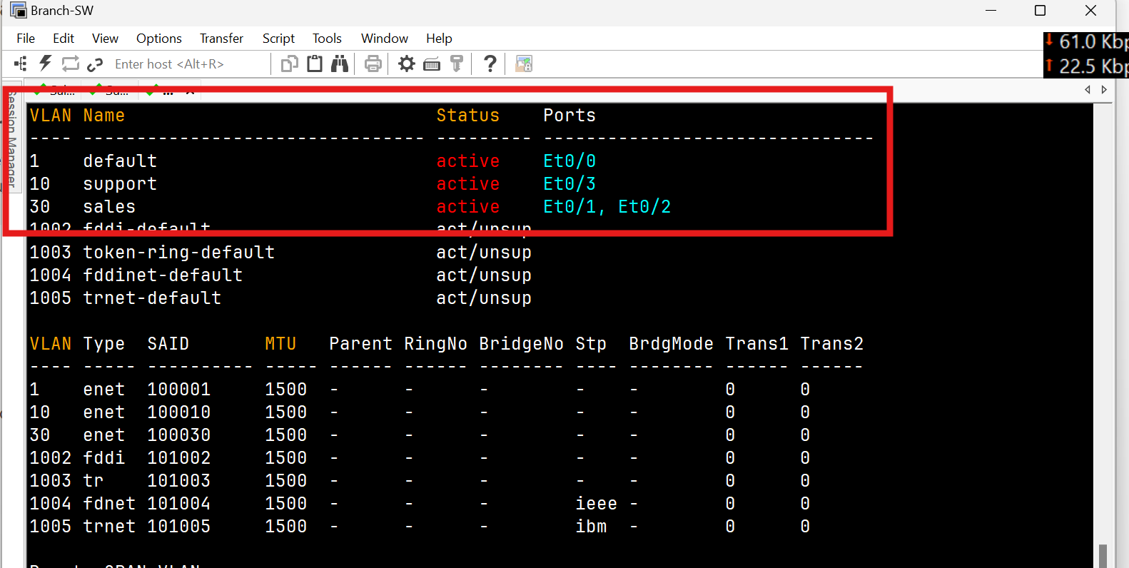
Trunk Port Configuration
North Switch
Branch-SW-North(config)#int e0/2
Branch-SW-North(config-if)#switchport trunk encapsulation dot1q
Branch-SW-North(config-if)#switchport mode trunk
Branch-SW-North(config-if)#switchport trunk  allowed vlan 10
Branch-SW-North(config-if)#switchport trunk native vlan 99 (for security reason change the native vlan to 99)
Branch-SW-North(config-if)#switchport nonegotiate
Branch-SW-North#wr
Verify Trunk
Branch-SW-North(config)#do show interfaces trunk
Branch-SW-North(config)#do show interface ethernet 0/2 switchport
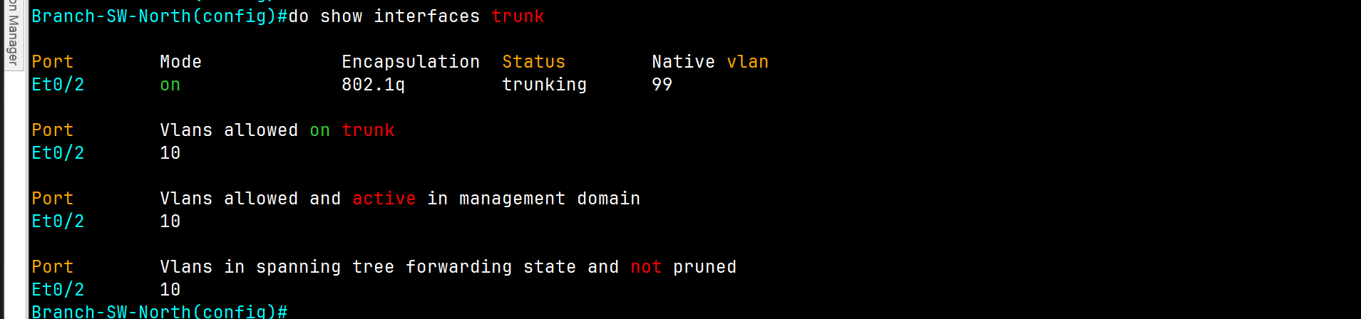
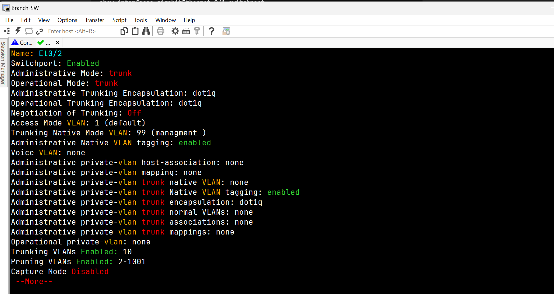
Core Switch
Core-SW(config)#vlan 99
Core-SW(config-vlan)#name managment
Core-SW(config-vlan)#vlan 9910
Core-SW(config-vlan)#support
Core-SW(config-vlan)#20
Core-SW(config-vlan)#name sales
Core-SW(config)#int range ethernet 0/0-3
Core-SW(config-if)#switchport trunk encapsulation dot1q
Core-SW(config-if)#switchport mode trunk
Core-SW(config-if)#switchport trunk allowed vlan 10,30
Core-SW(config-if)#switchport trunk native vlan 99
Core-SW(config-if)#switchport nonegotiate

Core-SW#wr
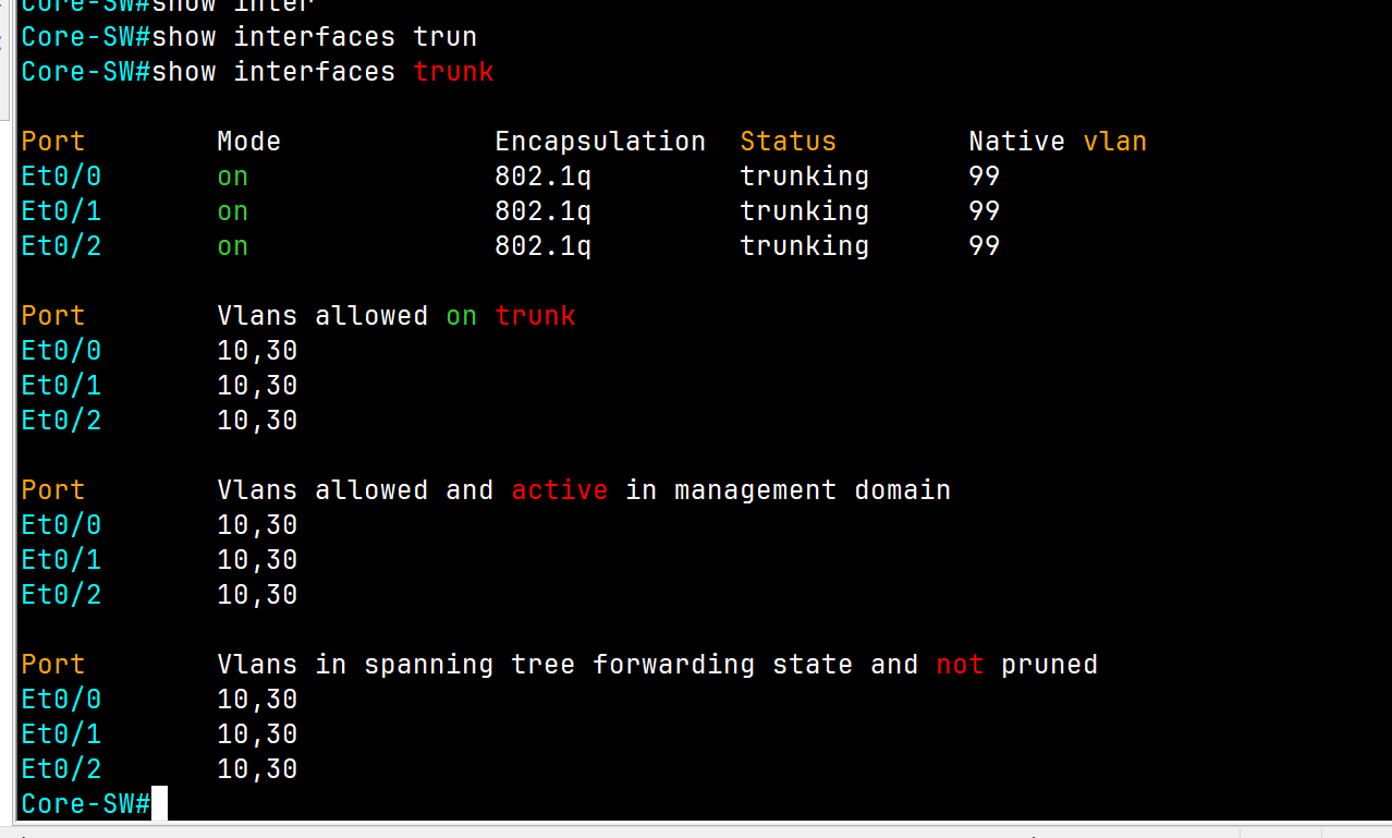
South Switch
Branch-SW-North(config)#int e0/0
Branch-SW-North(config-if)#switchport trunk encapsulation dot1q
Branch-SW-North(config-if)#switchport mode trunk
Branch-SW-North(config-if)#switchport nonegotiate
Branch-SW-North(config-if)#switchport trunkin  allowed vlan 10
Branch-SW-North(config-if)#switchport trunk native vlan 99 (for security reason change the native vlan to 99)
Branch-SW-North#wr
Finally, we have access between the same VLAN on different locations
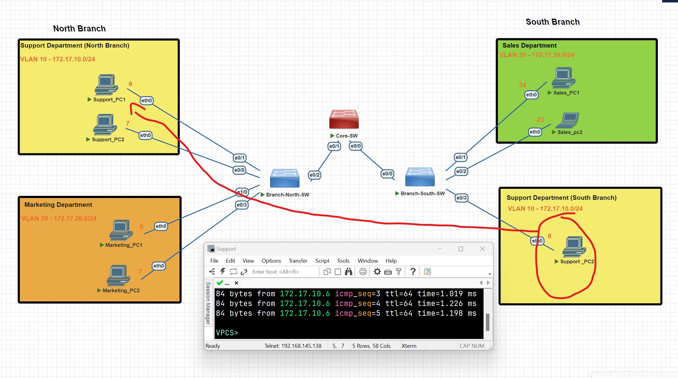
Router On Stick
To establish routing between VLANs, we configure a router using a technique called "Router on a Stick."
Configuring the Trunk on the Switch Port Connected to the Router
Core-SW(config)#int e0/2
Core-SW(config-if)#switchport trunk encapsulation dot1q
Core-SW(config-if)#switchport trunk native vlan 99
Core-SW(config-if)# switchport trunk allowed vlan 10,30
Configure the Router to establish routing between
router(config)#int fa 0/0
router(config-if)#int fa0/0.10
router(config-subif)#ip address 172.17.10.55 255.255.255.0
router(config-subif)#exit
router(config)#int fa0/0
router(config-if)#int fa0/0.30
router(config-subif)#encapsulation dot1Q 30
router(config-subif)#ip address 172.17.30.55 255.255.255.0
router(config-subif)#exit
router(config-if)#no shut
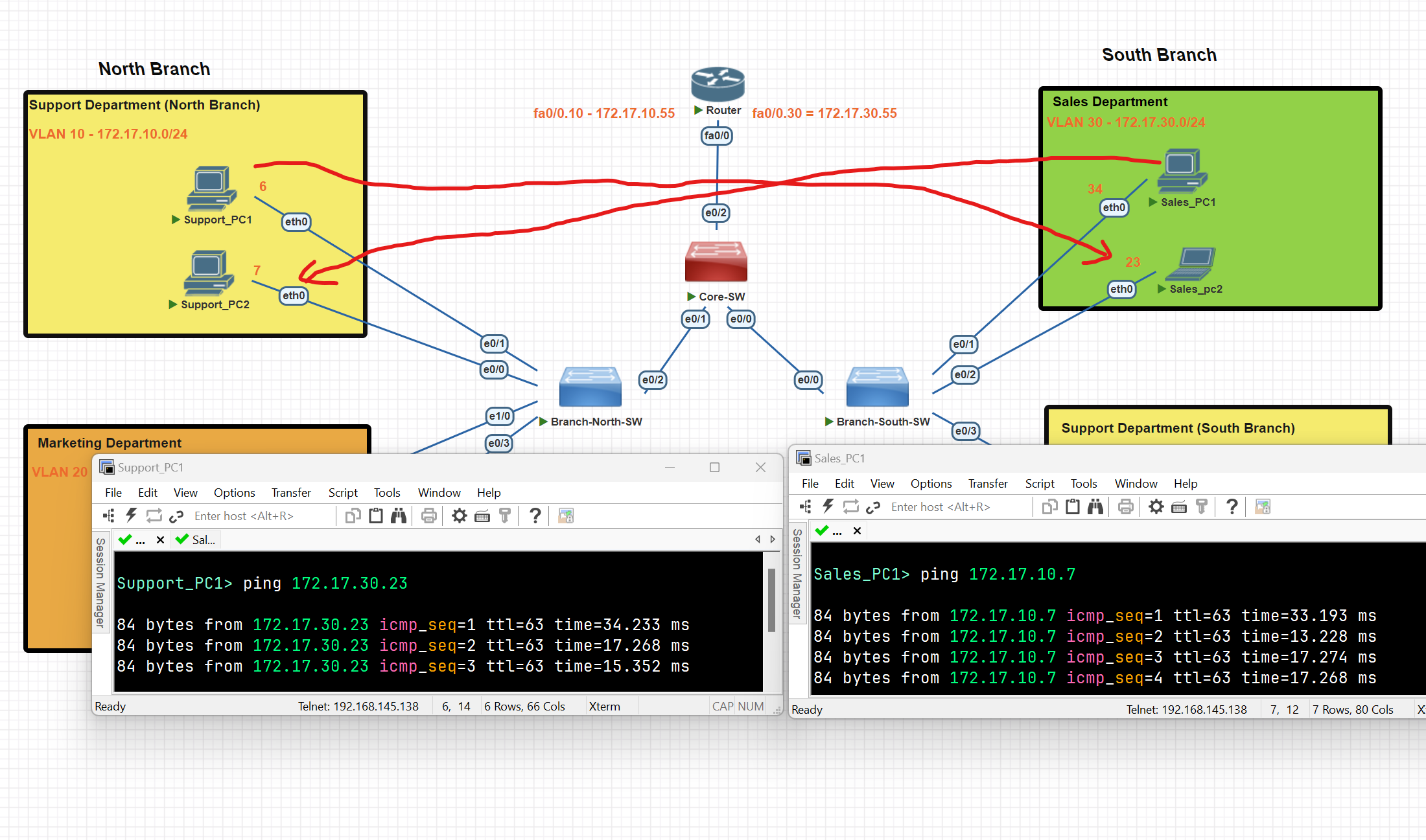
We have now successfully established connectivity between two distinct VLANs.
Spanning Tree Protocol (STP)
What is STP
Spanning Tree Protocol (STP) is a Layer 2 network protocol that prevents loops in networks with redundant links. It logically blocks physical loops in a Layer 2 network by placing redundant ports in a blocking state, essentially disabling the interface.
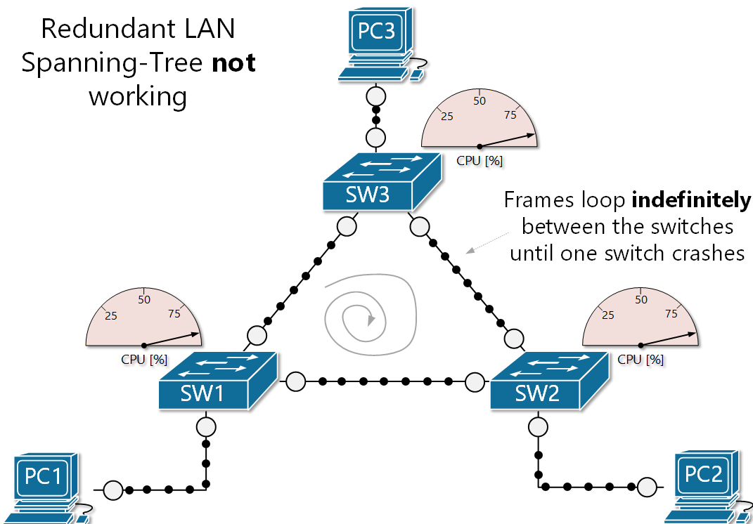
- Interfaces in a forwarding state behave normally, they send and receive all normal traffic.
- Interfaces act as backups that can enter a forwarding state if an active interface fails.
- Interfaces in a blocking state only send and receive STP messages (Called BPDUs= Bridge Protocol Data Units)
- By selecting which ports are forwarding and which ports are blocking, STP creates a single path to/from each point in the network.
- There is a set of processes that STP uses to determine which port should be forwarding and which should be blocking.
- STP-enabled switches send/receive Hello BPDUs out of all interfaces; the default timer is 2 seconds.
- If a switch receives a Hello BPDU on an interface, it knows that the interface is connected to another switch (routers, PCs, etc, do not use STP, so they do not send Hello BPDUs)
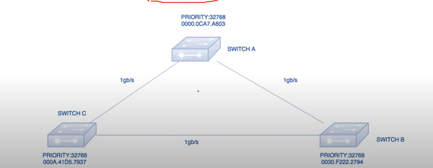
Bridge Priority Data Unit(BPDU): It contains the Bridge ID, the Sender’s bridge ID cost to the root bridge, and the Timer values on the root bridge.
All switches exchange BPDU in order to elect the root bridge. The switch with the lowest bridge ID, is elected as the root Bridge.
Bridge ID: an 8-byte field that combines the bridge priority (2 bytes) and Base Mac address(6 bytes) of a device. If there is a tie on bridge priority, then the base MAC address is considered.
Bridge Priority: The default priority value for all Cisco Switches is the decimal value 32768.
Root Bridge: The root bridge is the bridge with the lowest Bridge ID. All decisions, like which port is the root port (The port with the best path to the root bridge), are made from the perspective of the root bridge.
Path Cost: A switch may encounter one or more switches in the path to the root bridge. All the paths analyzed and the path with the lowest cost will be selected.
| Speed | Link Cost |
| 100 Mbps | 19 |
| 10 Mbps | 100 |
| 100 Gbps | 2 |
| 1 Gbps | 4 |
STP Ports
- Root Port(RP): The port on a non-root switch that has the shortest path to the root bridge. It forwards traffic to the root bridge.
- Designated Port: The designated port forwards traffic from a segment to the root bridge. All STP-enabled switches have one or more designated ports.
💡 Note: The root bridge only has designated ports.
Steps to a Loop-Free Topology
1-Selecting Root Bridge: When two switches are configured with the same priority and have the same extended system ID, the switch having the mac address with the lowest value, will have the Lower BID(Bridge ID) selected as the root bridge and no port of the switch blocked.
2-Select Designated Ports: All ports from the root bridge are called designated ports.
3-Select Root port:
- Lowest root cost
- Lowest neighbor bridge ID
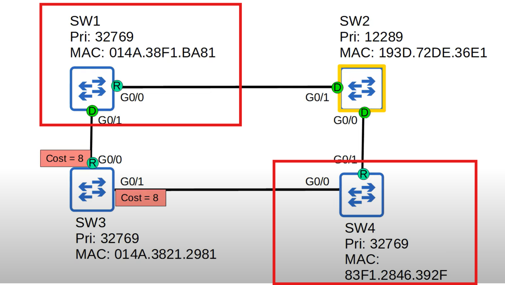
Switch 2 was selected as a root bridge, Switch 3 has the same cost from both sides, and which neighbour has the lowest Bridge ID will be selected as the root port in this diagram. SW1 has a lower Bridge ID.
- Lowest neighbor pot ID
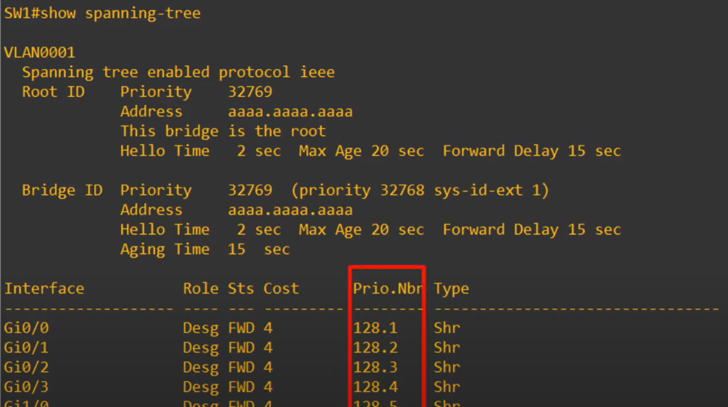
STP Port ID = Port priority(default 128**) + port number.** for example: Gi0/0 lower than Gi 0/1
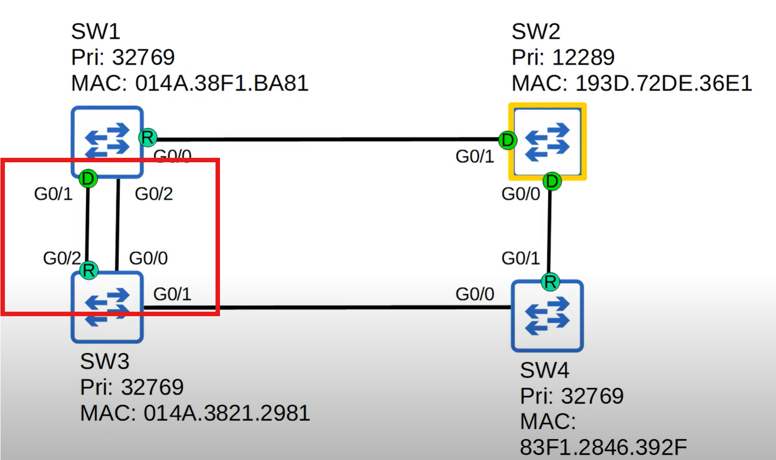
Switch 3 has two connections with SW1 and a lower port ID will selected as a root port G0/1 lower than G0/2.
💡 The neighbor switch's port ID is used to determine the tie, not the local switch's port ID.
4-Bock Port: After the root bridge is selected, one of the remaining switches with a high Mac address value should block one of the ports.
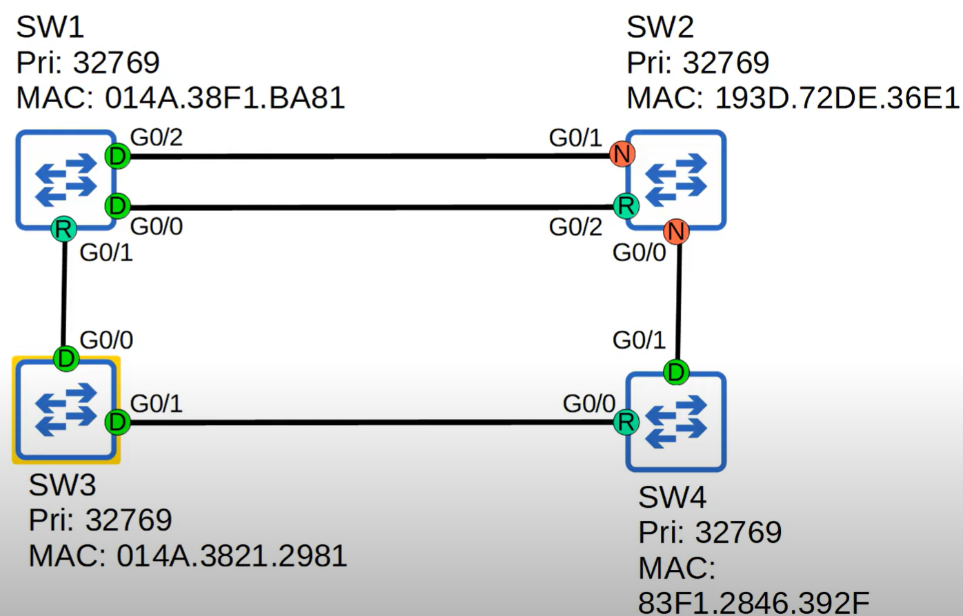
- Low Bridge ID selected, and SW3 is a root bridge.
- If SW2 has multiple paths with the same cost, the path through the neighbor with the lowest Bridge ID is selected.
- We have two connections between SW1 and SW2 Lowest neighbor port ID will be selected G0/0 smaller than G0/2.
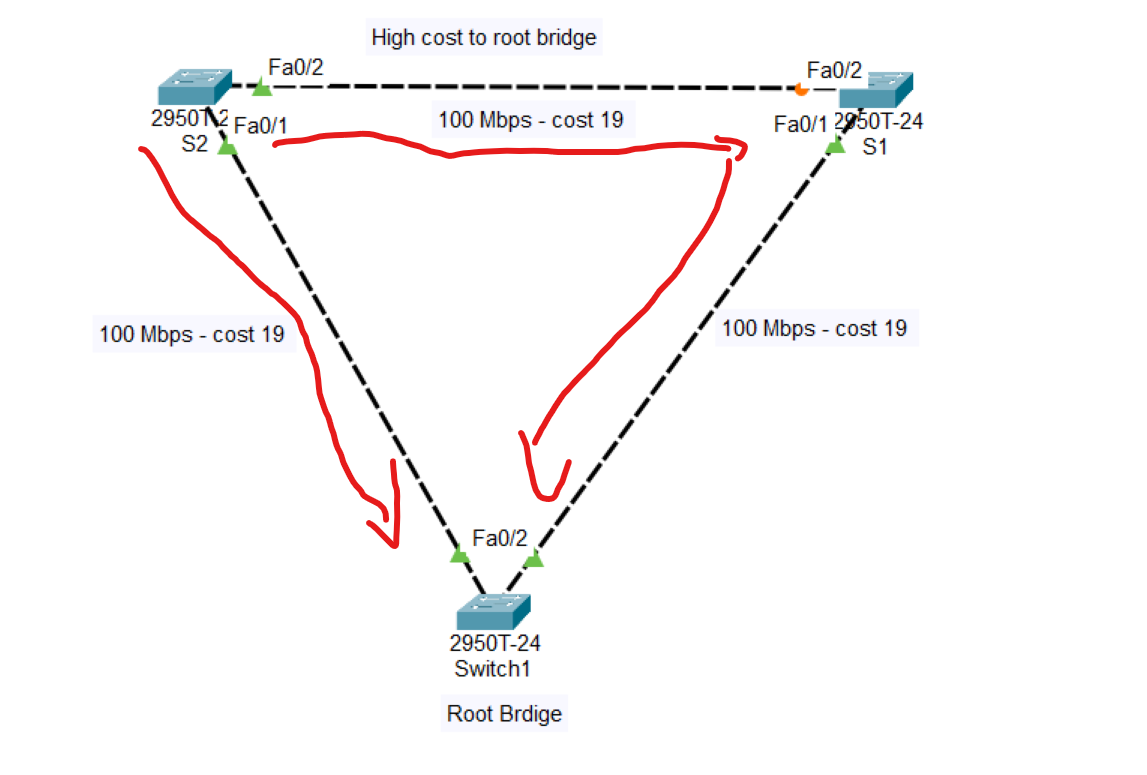
Note: Blocking port depends on the cost; for the best path to the root bridge, the cost should be low. cost can be determined by the type of cables connected to the switches
The cost of switch number 2 (S2) to the root bridge through S1 = 38.
But directly from S2 to the root bridge is 19, therefore, the Line between S1 to S2 is blocked.
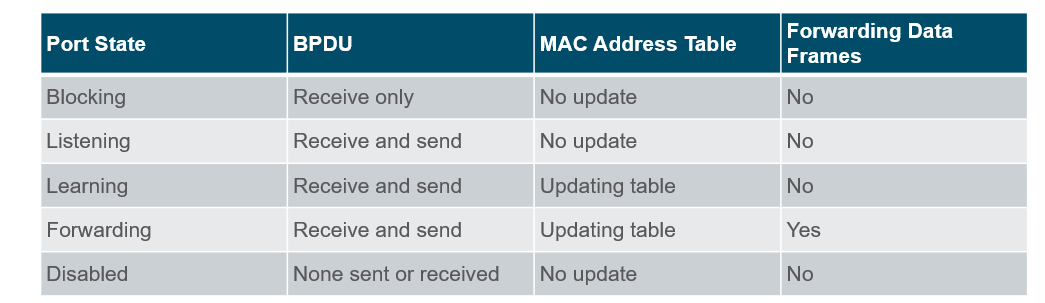
💡 Root/Designated ports remain stable in the Forwarding state.
Non-designated ports remain stable in the Blocking state.
Non-designated ports remain stable in the Blocking state.
How do you know which switch is a root bridge?
Switch#show spanning-tree
After writing this command, if the switch is selected as the root bridge in the Root ID shows this message: “ This is the root bridge“
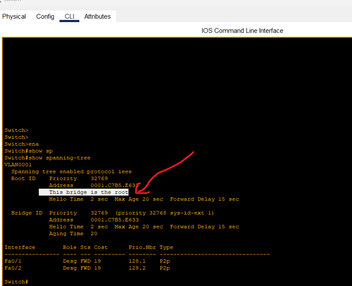
Also, the bridge root ports have the same role as designated ports.
Using the same command on the switch, one of the ports has been blocked.
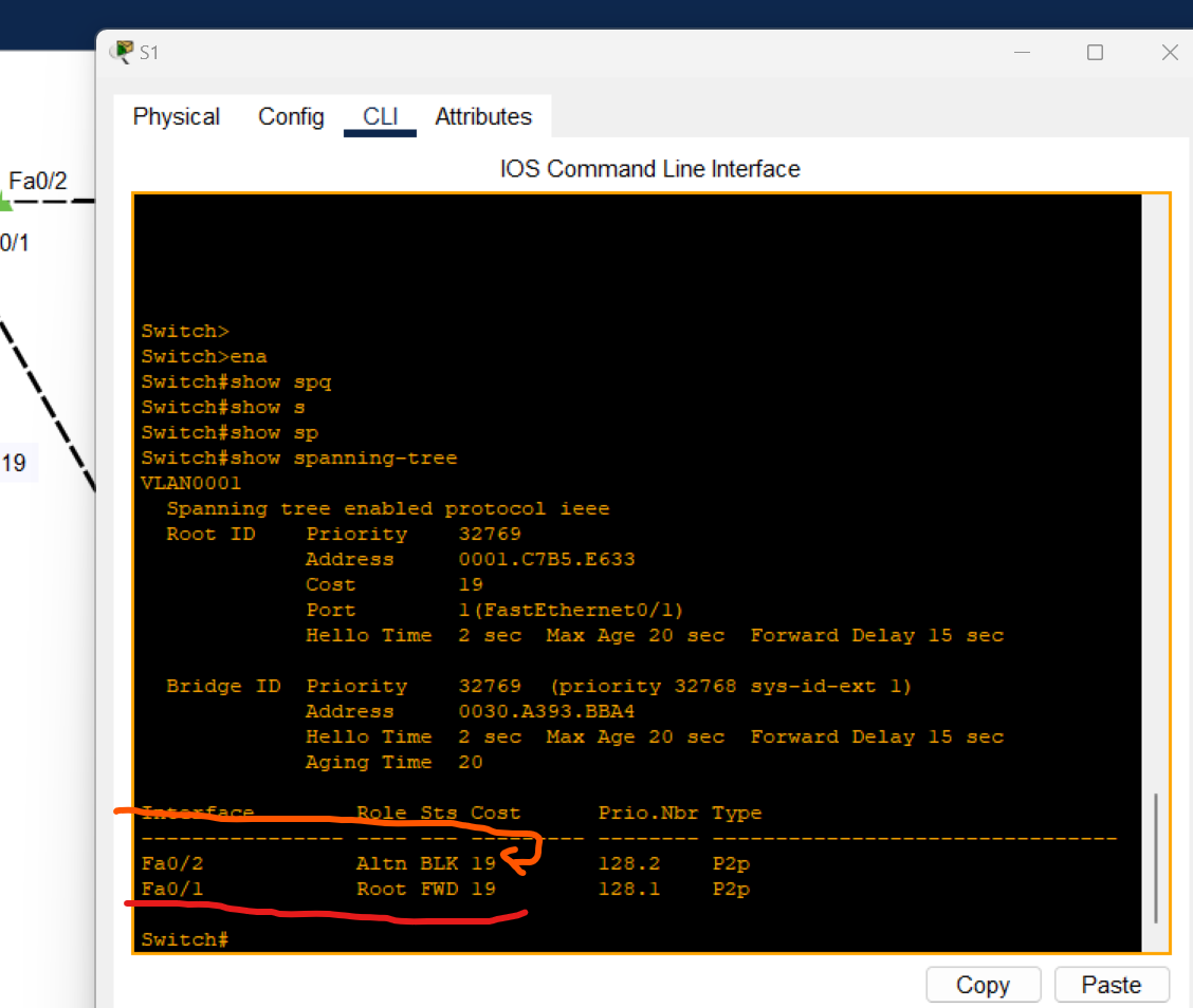
Spanning Tree Timers
| STP Timer | Purpose | Duration |
| Hello | How often Root Bridge sends hello BPDUs | 2Sec |
| Forward Delay | How long the switch will stay in the listening and learning state(each state 15 seconds = total 30 seconds) | 30Sec |
| Max Age | How long an interface will wait after ceasing to receive Hello BPDUs to change the STP topology. | 20Sec |
Port Fast and BPDU guard
- PortFast is a Cisco Feature for PVST+ environments. When a switch port is configured with port fast, that port transitions from blocking to the forwarding state immediately, bypassing the usual 802.1D STP transition states(the Listening and learning state).
⚠️ If used, it must be enabled only on ports connected to end hosts.
If enabled on a port connected to another switch, it could cause a layer 2 loop.
Port Fast Configuration
Enable Port Fast per Interface
s1(config)# interface FastEthernet 0/1
s1(config-if)# spanning-tree portfast
Disable port fast on an interface
s1(config)# interface FastEthernet 0/1
s1(config-if)# spanning-tree portfast disable
Enable port fast on all access ports (not trunk ports)
s1(config)# spanning-tree portfast default
Portfast is a great feature for getting a switch port connected to an end host like a PC running quickly without having to wait for 30 seconds.
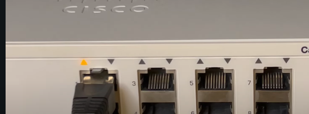
When plugging the cable into the switch port, we should wait for 30 Seconds for the listening and learning state (orange light). After that, the switch could forward data from the mentioned port.
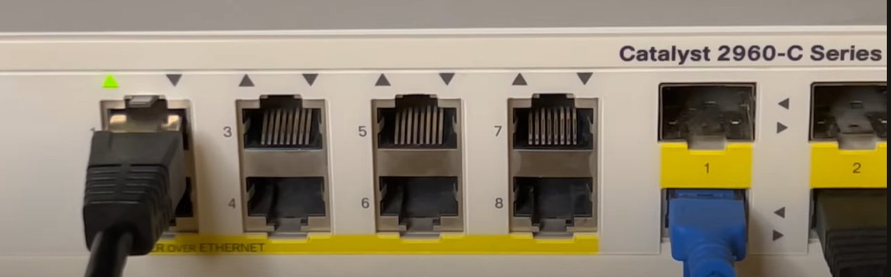
After enabling portfast on the switch port, when the cable is plugged in, the switch immediately starts forwarding (Indicated by a Green Light) and ignores the listening and learning states.
BPDU Guard
- BPDU Guard: This is a feature used to protect the Layer 2 Spanning Tree Protocol (STP) topology from BPDU-related attacks. When a BPDU Guard-enabled port receives a BPDU from the connected device, BPDU Guard disables the port and puts it into the
errdisablestate.
For example, if PortFast is enabled on interface G0/3 for end-user devices, and an end-user mistakenly connects a switch to that port instead of a PC, BPDU Guard will protect the STP topology by automatically disabling the port upon receiving BPDUs.
BPDU Guard should be configured on:
- Access ports connecting to end devices (workstations, printers, etc.).
- Ports connecting to servers or virtualization hosts that do not participate in the STP topology.
⚠️ When used alongside PortFast, BPDU Guard ensures that an access port remains stable and does not inadvertently participate in the spanning tree, preventing potential topology changes.
BPDU Guard protects the network from unauthorized switches being connected and participating in STP.
It can be configured separately from PortFast, but they are typically used together on edge/access ports.
BPDU Guard-enabled ports do not send BPDUs. If a BPDU is received, the port is placed in
error-disabledstate.
- BPDU Guard protects the network from unauthorized switches being connected and participating in STP.
- It can be configured separately from PortFast, but they are typically used together on edge/access ports.
- BPDU Guard-enabled ports do not send BPDUs. If a BPDU is received, the port is placed in
error-disabledstate.
Enable BPDU Guard Per Interface
s2(config)# interface FastEthernet 0/1
s2(config-if)# spanning-tree bpduguard enable
s2(config-if)# end
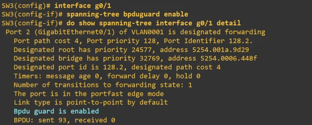
Enable BPDU Guard on all portfast interfaces
s2(config)# spanning-tree porfast bpduguard default
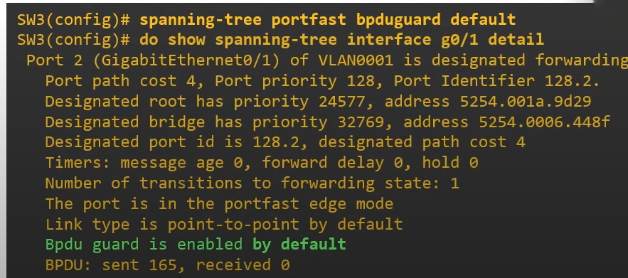
Recovery from BPDU Guard:
Manually Recovery
If a port is errdisableDue to BPDU Guard, it can be recovered manually or automatically by using the following command
s2(config)#interface FastEthernet 0/1
s2(config-if)#shutdown
s2(config-if)#no shutdown
Automatically Recovery
s2#show errdisble recovery
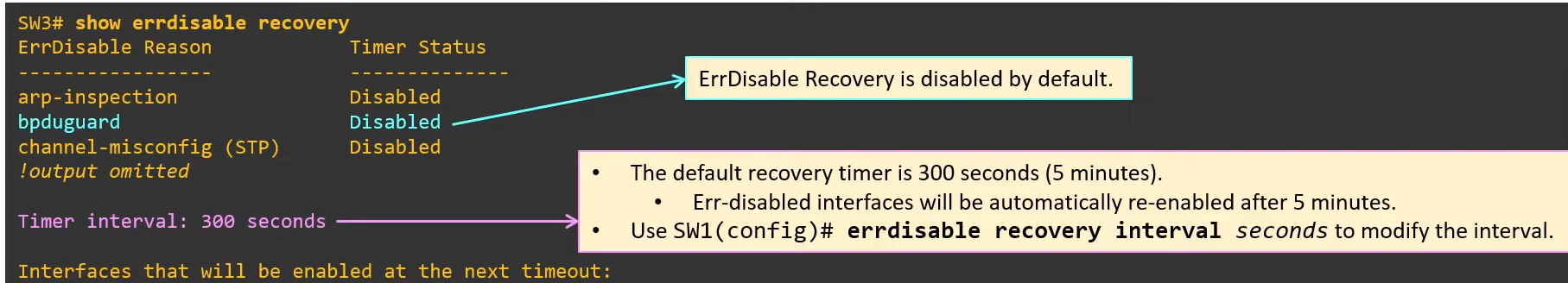
s2(config)#errdisable recovery cause bpdugurad
s2(config)#do show errdisable recovery
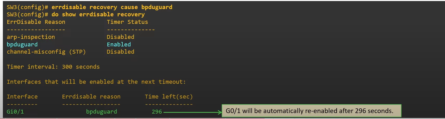
⚠️ If you didn’t solve the problem and the port is still connected to the switch and receives BPDU messages, the port will be disabled again.
💡 Best practice:
Use PortFast + BPDU Guard on all access ports.
Never enable on trunk ports.
- Use PortFast + BPDU Guard on all access ports.
- Never enable on trunk ports.
BPDU Filter
Prevent a port from sending BPDU messages
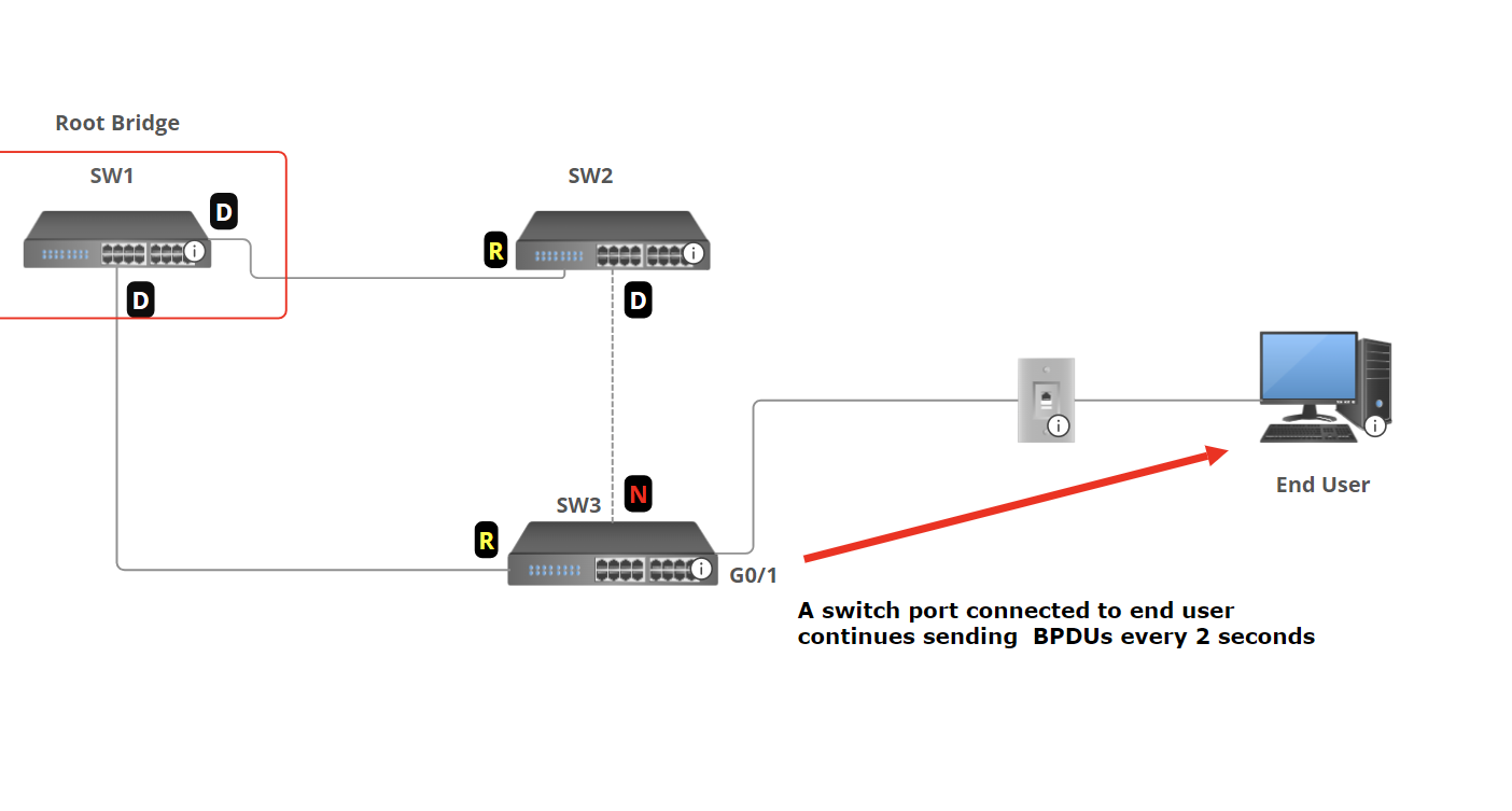
If the port doesn't connect to a switch, sending BPDUs is unnecessary and undesirable for a couple of reasons:
- Sending BPDUs uses some bandwidth and processing power on the switch.
- BPDUs contain information about the LAN’s STP topology. (You should avoid sending this information to end users)
BPDU Filter solves this by preventing the port from sending BPDUs.
Enable BPDU Filter Per Interface
s2(config-if)# spanning-tree bpdufilter enable
- The port will not send BPDUs.
- The port will ignore any BPDUs it receives.
- In effect, this disables STP on the port. Use with caution
Enable BPDU Filter on all interfaces (Global Mode)
s2(config)# spanning-tree portfast bpdufilter default
- BPDU filter will be activated on all portfast-enabled ports.
- The port will not send BPDU packets.
Disable BPDU filter per port
s2(config-if)# spanning-tree bpdufilter disable
💡 Enable PBDU filter by default (Global Config Mode). This is highly recommended
BPDU Guard and BPDU Filter can be enabled on the same port at the same time.
- If BPDU Filter is enabled in global config mode and the port receives BPDU:
- BPDU filter will be disabled.
- BPDU Guard will be triggered( errdisbale the interface).
- IF BPDU Filter is enabled in Interface config mode and the port receives BPDU:
- The BPDU will be ignored.
- BPDU Guard will not be triggered.
💡 Caution: Do not configure a port with BPDU Guard and BPDU Filter. Enabling both on the same interface effectively cancels the BPDU Guard feature. Specifically, a port configured with both features will not error-disable the port when a BPDU is received. Instead, it will default to the BPDU Filter and simply ignore the BPDUs.
Root guard
Root Guard is a feature in Spanning Tree Protocol (STP) that prevents a port from becoming a root port if it receives superior BPDUs (A BPDU that has a lower Bridge ID). When a switch port configured with Root Guard receives a BPDU that indicates a better root bridge (one with a lower bridge ID), the port is disabled and placed into a root-inconsistent state. This action enforces the current root bridge and ensures that the topology remains stable by preventing unauthorized or unintended switches from claiming root bridge status
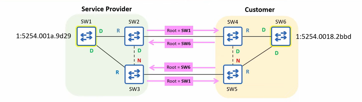
In this example, the Service Provider's switches are connected to the customer's switches, and the customer's root bridge ID is lower than the Service Provider's root bridge ID. The Service Provider wants to protect its STP topology and prevent it from being affected by the customer's root bridge
Root Guard can be configured to protect the STP topology by preventing the service provider switch from accepting superior BPDUs from outside of service provider control.
Root Guard Configuration
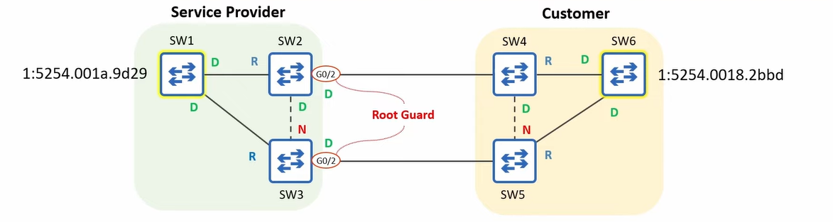
Root Guard will be configured on the ports connected to switches outside of the control.
s2(config-if)# spanning-tree guard root
💡 - Loop Guard does not have a global default command
If a Root Guard-enabled port receives a BPDU, it will enter the broken state, effectively disabling it.
The port will not be able to forward data frames and will discard any frames it receives.
SW1, SW2, and SW3 won’t accept SW6 as a root Bridge.
To re-enable the ports disabled by Root Guard, you must solve the issue that disabled the port.
The Disabled ports must stop receiving superior BPDUs.
Tell the customer to increase the priority value of their switch.Ports in root-inconsistent state recover automatically after the port stops receiving superior BPDUs. Unlike BPDU guard, manual intervention is not required.
- Loop Guard does not have a global default command
- If a Root Guard-enabled port receives a BPDU, it will enter the broken state, effectively disabling it.
- The port will not be able to forward data frames and will discard any frames it receives.
- SW1, SW2, and SW3 won’t accept SW6 as a root Bridge.
- To re-enable the ports disabled by Root Guard, you must solve the issue that disabled the port. The Disabled ports must stop receiving superior BPDUs. Tell the customer to increase the priority value of their switch.
- Ports in root-inconsistent state recover automatically after the port stops receiving superior BPDUs. Unlike BPDU guard, manual intervention is not required.
Loop Guard
Loop Guard is a Spanning Tree Protocol (STP) feature designed to prevent Layer 2 loops, especially those caused by unidirectional link failures (e.g., a broken fiber pair where only one direction fails)
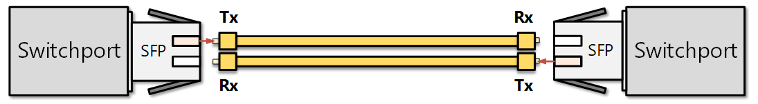
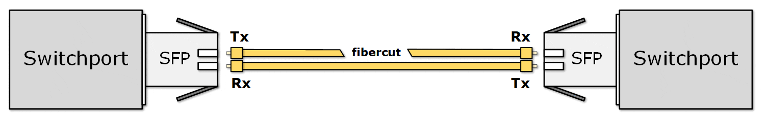
Unidirectional Fiber cut If a port stops receiving BPDUs, Loop Guard places that port into a loop-inconsistent blocking state to prevent it inadvertently transitioning to forwarding and forming a loop
💡 Note: Loop guard and root guard should be configured together. While Root Guard protects against unauthorized switches attempting to become the root bridge, Loop Guard protects against unintended loops caused by link failures. Together, these features help maintain the integrity and stability of the spanning tree topology.
Loop Guard Per Interface Configuration
S4(config-if)#spanning-tree guard loop
💡 Unlike BPDU Guard or Root Guard, there is no global command (like
spanning-tree loopguard default).
STP Versions
As you can see, when a loop occurs in the network, STP needs some time to block one of the switch ports. We are waiting for a few seconds until the green light has been changed to green. After that, STP is updated, and 5 generations of it are created.
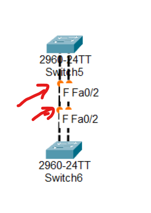
- Common Spanning Tree (CST) or IEEE 802.1D (Standard)
- Rapid Spanning Tree Protocol (RSTP) or IEEE 802.1W (Standard)
- Per VLAN Spanning Tree + (PVST+) by Cisco
- Rapid Per VLAN Spanning Tree+ (RPVST+) by Cisco
- Multiple Spanning Tree IEEE 802.1s. (Standard)
STP (802.1D) VS RSTP(802.1W)
| Feature | STP (802.1D) | RSTP (802.1w) |
| Standard | IEEE 802.1D | IEEE 802.1w |
| Convergence Time | 30–50 seconds | 1–10 seconds |
| Port Roles | Root, Designated, Blocked | Root, Designated, Alternate, Backup, Discarding |
| Port States | Blocking, Listening, Learning, Forwarding, Disabled | Discarding, Learning, Forwarding |
| BPDU Handling | BPDUs only sent by Root Bridge | BPDUs are sent by all switches every 2s |
| Port Fast Equivalent | Not native (uses Cisco "PortFast") | Natively supports edge ports (like PortFast) |
| Loop Recovery | Slow, waits for timers | Fast, uses handshake mechanism |
| Typical Use | Older networks | Modern networks needing faster failover |
Alternate Port: Alternate ports are in a discarding state and quickly transition to the forwarding state when the root port path fails. Alternate ports are typically found on non-root bridges and help ensure rapid convergence in the event of a link failure.
Backup Port: Backup ports serve as a backup to designated ports on a switch. Backup ports discard traffic and immediately transition to the forwarding state if the designated port fails.
| Port Role | Direction | Typical State | Purpose |
| Root Port | Best path to Root | Forwarding | Main path to root bridge |
| Designated Port | Best path to Segment | Forwarding | Forwarding for that LAN |
| Alternate Port | Backup path to Root | Discarding | Replaces Root Port if it fails |
| Backup Port | Backup path to Designated | Discarding | Replaces Designated Port if it fails |
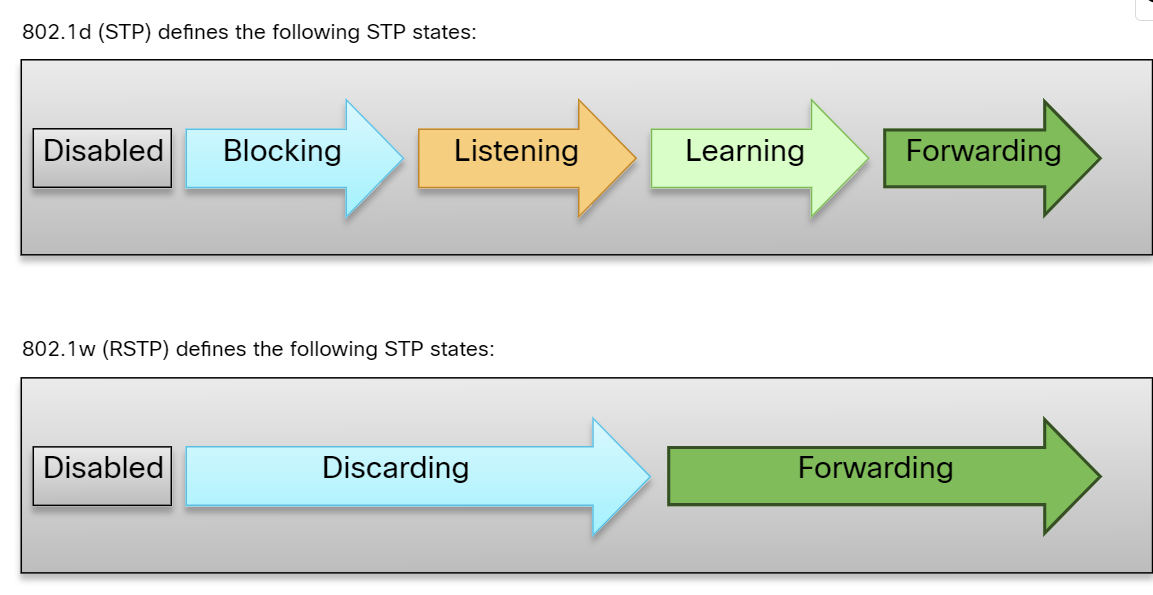
Per VLAN Spanning Tree+ (PVST+)
PVST+ is a proprietary Cisco feature that finds the root bridge per V. LAN. It is the default version of STP from Cisco. It finds separate 802.1d spanning-tree instances for each VLAN. It also provides backward compatibility with 802.1d or CST. This is more optimized for the IEEE because it provides optimal path selection as a separate instance of STP per VLAN is found. This is as slow as CST.
Advantages:
- Provide more optimization on the performance of a network than CST, as it selects the root bridge per VLAN.
- Bandwidth consumption is less than CST.
- Optimum load balancing is achieved.
Disadvantages:
- This is as slow as CST, and the convergence time is slow. By default, Cisco switches take 50 seconds to converge.
- More resources (CPU and memory) are required.
- Rapid Per VLAN Spanning Tree + (RPVST+): This is a spanning tree standard by Cisco that provides faster convergence than PVST+ and finds a separate instance of 802.1w per VLAN. It requires much more CPU and memory than other STP standards.
802.1s(Multiple Spanning Tree)
- 802.1s(Multiple Spanning Tree): This standard is developed by IEEE, in which grouping of VLANs is done, and for every single group, RSTP is run. This is basically a spanning tree protocol running over another spanning tree protocol.
Advantages:
- High redundancy.
- Load balancing can be achieved.
- Lower CPU and Memory usage is required
Disadvantages:
- More configuration is required, and not easy to implement.
Spanning Tree Configuration
s3(config)# spanning-tree vlan 20 root primary
s3(config)# spanning-tree vlan 10 root secondary [secondary switch add when primary root bridge removed the second one be a root bridge]
s3(config)# spanning-tree vlan 20 priority 4096
 s3# show spanning-tree
 s3# conf t
 s3(config)#spanning-tree mode rapid-pvst
 s3# show spanning-tree vlan 10
Which one is the first step in STP operation?
• Select the Root Bridge ✅
Which one is the last step in STP operation?
• Block all Non-Root & Non-DP’s ✅
What is the maximum number of Root Ports that each Cisco switch can have in the STP Topology?
• 1 ✅
D. Learning E. Forwarding
D. Learning
B. (In RSTP terms, this means discarding state (blocking equivalent in classic STP). The Backup Port is exactly this: a redundant path toward the designated bridge on a shared segment.)
D
D
B
Correct answers: A and E
panning tree enabled protocol rstp” ➜ on Cisco that means Rapid PVST+
Under Root ID, it shows Cost 19 and Port 1 (FastEthernet 2/1). When a switch is not the root, the interface listed here is the root port (the port used to reach the root bridge).
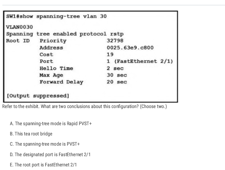
A E
B
EtherChannel
What is EtherChannel?
- EtherChannel(link aggregation) is a port link aggregation technology in which multiple physical port links are grouped into one logical link. It provides high speed and redundancy, load sharing, and increased bandwidth between switches, routers, and servers.
- A maximum of 8 links can be aggregated.
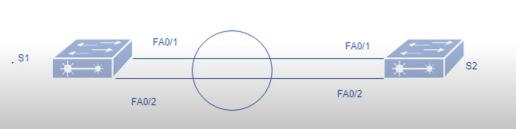
Note: only an even number of cables can be used between the switches, for example 2-4-6 cables, not odd numbers like 1-3-5.
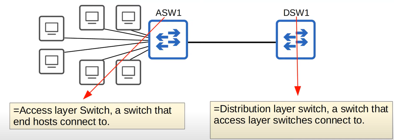
When the bandwidth of the interfaces connected to end hosts is greater than the bandwidth of the connection to the distribution switch(es), this is called oversubscription. Some oversubscription is acceptable, but excessive oversubscription can cause congestion. To address this, the network administrator adds multiple links between the access switch and the distribution switch.”
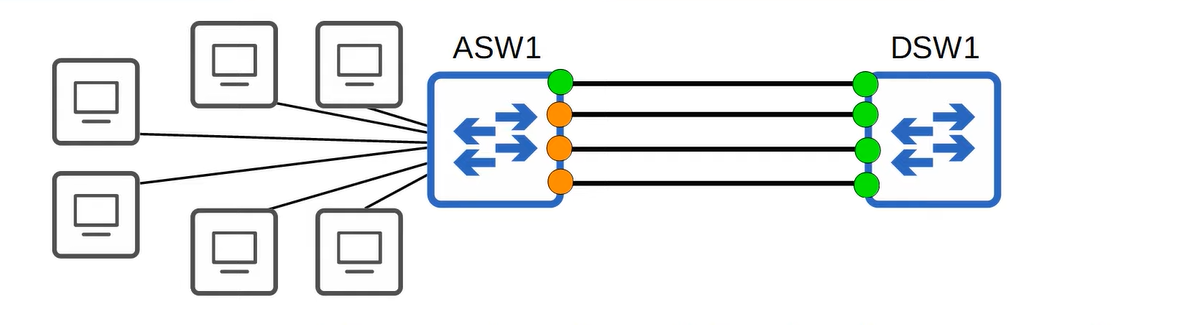
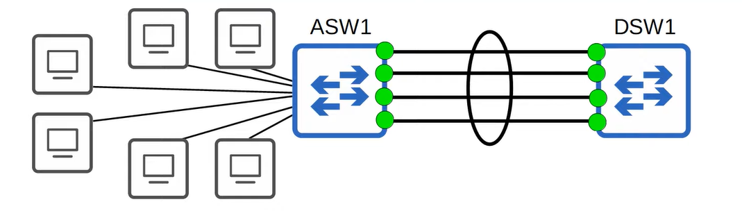
EtherChannel groups multiple interfaces together to act as a single, high-bandwidth link. Without EtherChannel, in a redundant link environment, each link would be treated as a separate entity by Spanning Tree Protocol (STP). This would result in only one link being active, while the others remain in a blocking state
Requirement
- Same duplex.
- Same speed
- Same VLAN configuration
- Switch port modes should be the same ( access or trunk mode).
Port Aggregation Protocol(PAgP)
Port Aggregation Protocol (PAgP) is a Cisco proprietary protocol used with an EtherChannel.
There are different modes in which you can configure your interface.
- On: no negotiation takes place. (No protocol used.)
- Desirable: Actively negotiates EtherChannel.
- Auto: Passive, waits for the other side to initiate.
- Off: No EtherChannel configured on the interface.
| SW1 | SW2 | Channel Established |
| ON | ON | Yes |
| Auto/Desirable | Desirable | Yes |
| On/Auto/Desirable | Not Configured | No |
| ON | Desirable | No |
| Auto/on | Auto | No |
💡 Up to 8 Interfaces can be formed into a single EtherChannel (LACP allows up to 16 links, but only 8 will be active, the other 8 will be in standby mode, waiting for an active interface to fail)
Link Aggregation Control Protocol(LACP)
Link Aggregation Control Protocol is an IEEE protocol, originally defined in 802.3ad, used to form an EtherChannel. This protocol is almost similar to Cisco PAgP. There are different modes in which you can configure your interface.
- ON: In this mode, the interface will be a part of EthernetChannel, but no negotiation takes place.
- Active: Actively negotiates EtherChannel.
- Passive: Passive, waits for initiation
- Off: No EtherChannel configured on the interface.
| SW1 | SW2 | Channel Established |
| On | ON | Yes |
| Active/Passive | Active | Yes |
| On/Active/Passsive | Not Configured | NO |
| ON | Active | NO |
| Passive/ON | ON | NO |
💡 ON mode only works with ON mode ( ON+ Active or On + Desirable will not work)
ASW1(config-if-range)#channel-group [1-255] number mode (ative for LACP, Desrible for PAgP)
What is the status of the port channel if LACP is misconfigured?
Disabled ✅
You have configured three trunk ports in an EtherChannel group. What will happen when one port in the grouping fails?
The channel cost has increased. ✅ (Because the EtherChannel group has lost some bandwidth, the cost of the grouped link is increased.)
C ( Not D because D adds 300 and removes other VLANs)
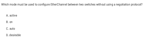
B
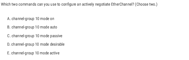
D and E
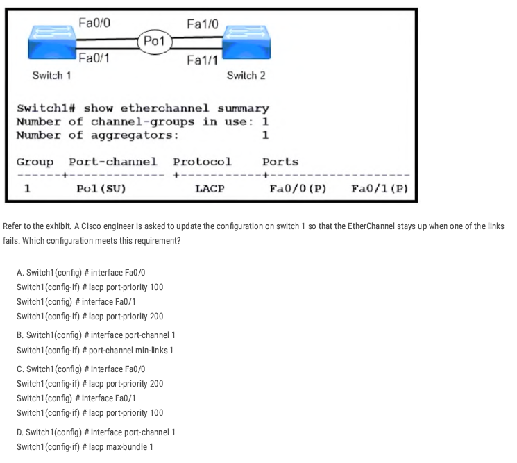
B
Creating the port-channel interface and using port-channel min-links 1 tells the switch to keep the Port-Channel (Po1) operational as long as at least one member link is up.
EtherChannel LAB
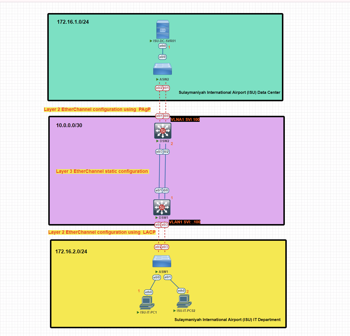
In this scenario, we will implement EtherChannel Layer 2 and Layer 3 with different types of EtherChannel protocols, Static, PAgP, and LACP, for this topology.
EtherChannel Configuration on Access Switch 1 Using LACP Protocol
ASW1#conf t
ASW1(config)#interface range e0/2-3
ASW1(config-if-range)#channel-group 1 mode active
ASW1(config)#int po1 [port-channel 1]
ASW1(config-if)#switchport trunk encapsulation dot1
ASW1(config-if)#switchport mode  trunk
Verify EtherChannel Configuration on Access Switch 1
ASW1#show etherchannel summary
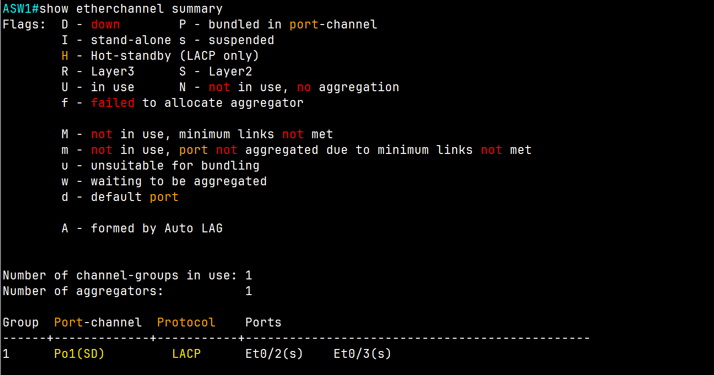
EtherChannel Configuration on Distribution Switch 1 Using LACP Protocol (Access Switch Side)
DSW1#conf t
DSW1(config)#int range e0/2-3
DSW1(config-if-range)#channel-group 1 mode active
DSW1(config)#int po1
DSW1(config-if)#switchport trunk encapsulation dot1q
DSW1(config-if)#switchport mode trunk
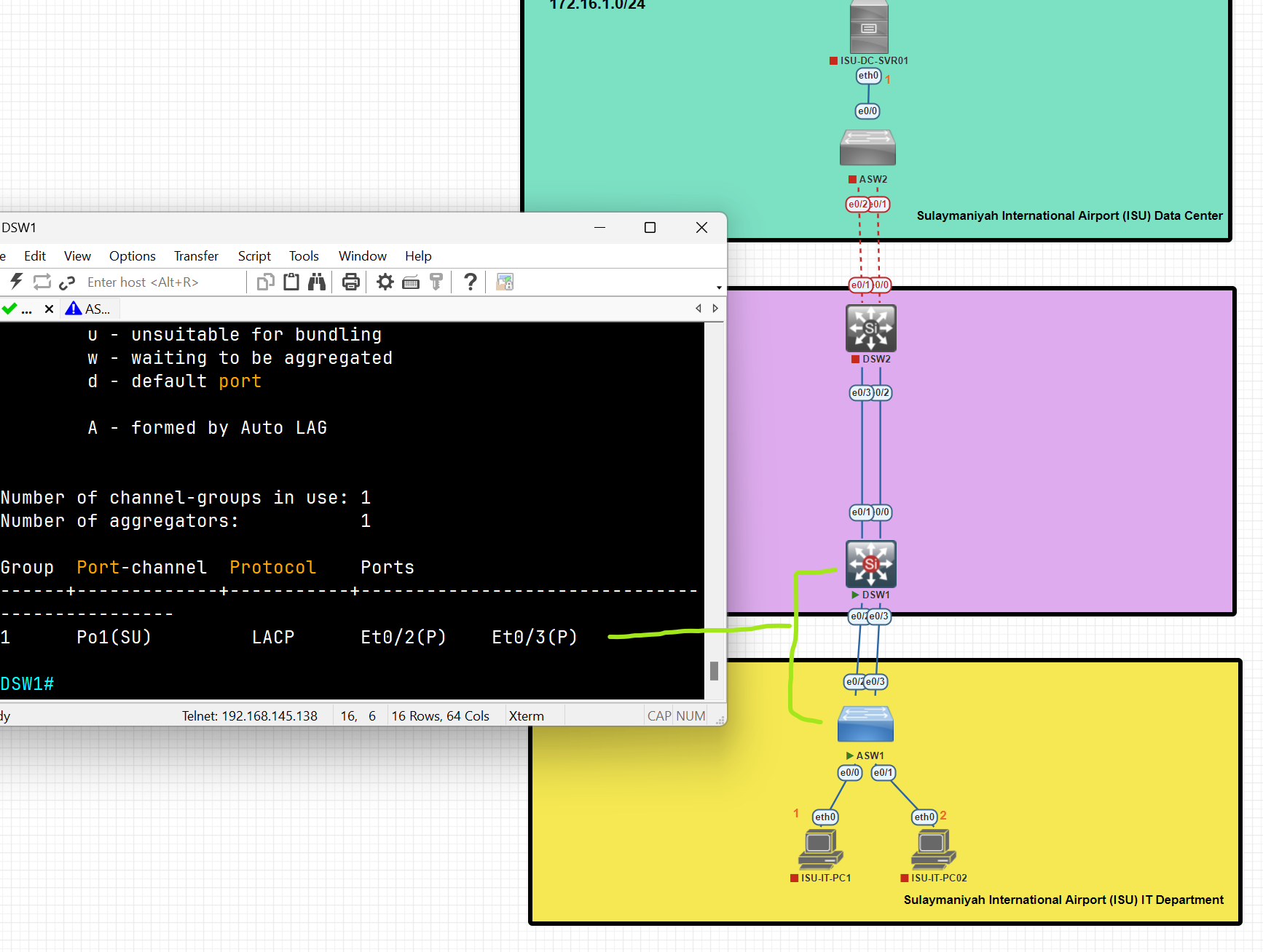
An EtherChannel connection has been established between the Access and Distribution switches using LACP.
Configure SVI (Switch Virtual Interface) as a Default gateway
DSW1(config)#int vlan 1
DSW1(config-if)#ip address 172.16.2.100 255.255.255.0
DSW1(config-if)#no shutdown
A Switch Virtual Interface (SVI) is a logical interface on a network switch that enables Layer 3 functionality for a VLAN. It allows the switch to perform routing between VLANs and provides IP connectivity for the VLAN.
💡 An EtherChannel is just a link bundle. A default gateway must be an IP address on a Layer-3 interface, not a link.
EtherChannel Configuration on Access Switch 2 Using PAgP Protocol
ASW2(config)#int range e0/1-2
ASW2(config-if-range)#channel-group 1 mode desirable
ASW2(config-if-range)#int po1
ASW2(config-if)#switchport trunk encapsulation dot1q
ASW2(config-if)#switchport mode trunk
ASW2#show etherchannel summary
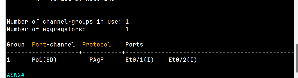
EtherChannel Configuration on Distribution Switch 2 Using PAgP Protocol (Access Switch Side)
DSW2(config)#int range e0/0-1
DSW2(config-if-range)#channel-group 1 mode desirable
DSW2(config-if-range)#no shutdown
DSW2(config-if-range)#int po1
DSW2(config-if)#switchport trunk encapsulation dot1q
DSW2(config-if)#switchport mode trunk
DSW2#show etherchannel summary
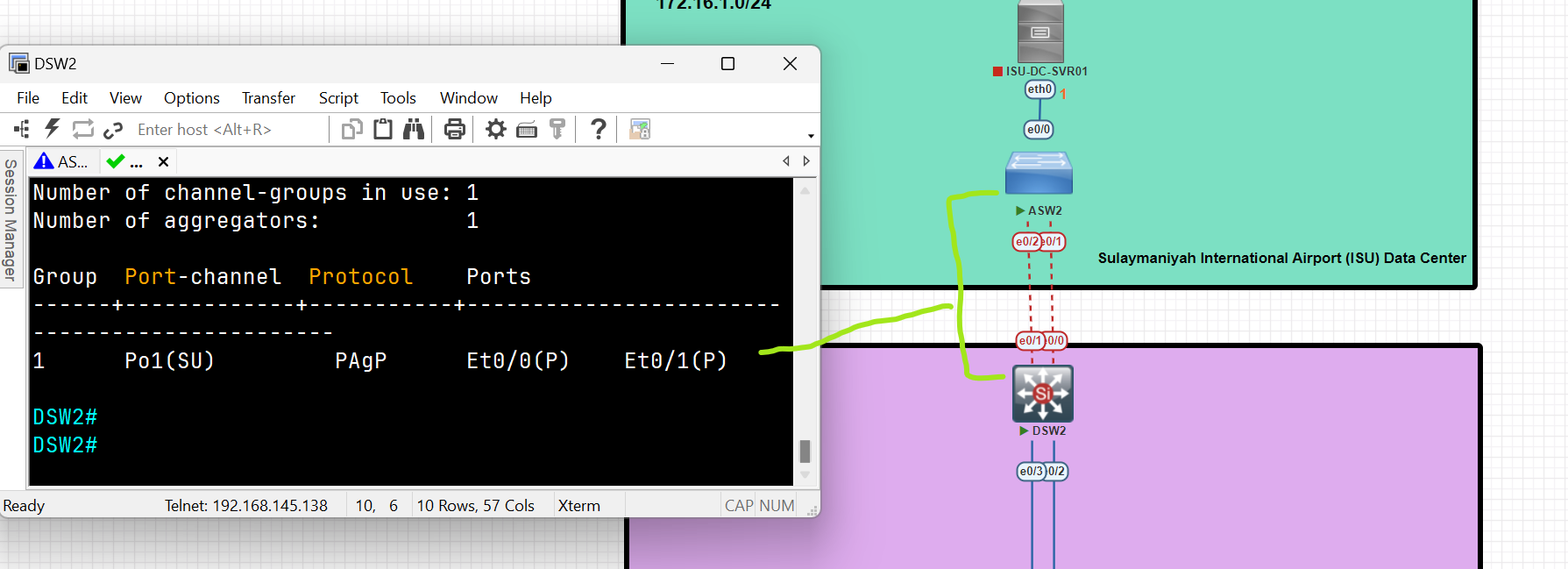
Configure SVI (Switch Virtual Interface) as a Default gateway
DSW2(config)#int vlan 1
DSW2(config-if)# ip address 172.16.1.100 255.255.255.0
DSW2(config-if)#no shut
Layer 3 EtherChannel Configuration between two Layer 3 Switches
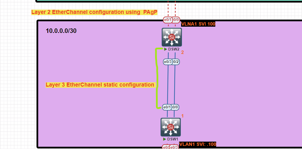
Distribution Switch 1 Configuration
DSW1(config)#int range e0/0-1
DSW1(config-if-range)#no switchport /change to routed port/
DSW1(config-if-range)#channel-group 2 mode on
DSW1(config-if-range)#no shutdown
DSW1(config-if-range)#int po2
DSW1(config-if)#ip address 10.0.0.1 255.255.255.252
Distribution Switch 2 Configuration
DSW2(config)#int range e0/02-3
DSW2(config-if-range)#no switchport
DSW2(config-if-range)#channel-group 2 mode on
DSW2(config-if-range)#no shutdown
DSW2(config-if-range)#int po2
DSW2(config-if)#ip address 10.0.0.2 255.255.255.252
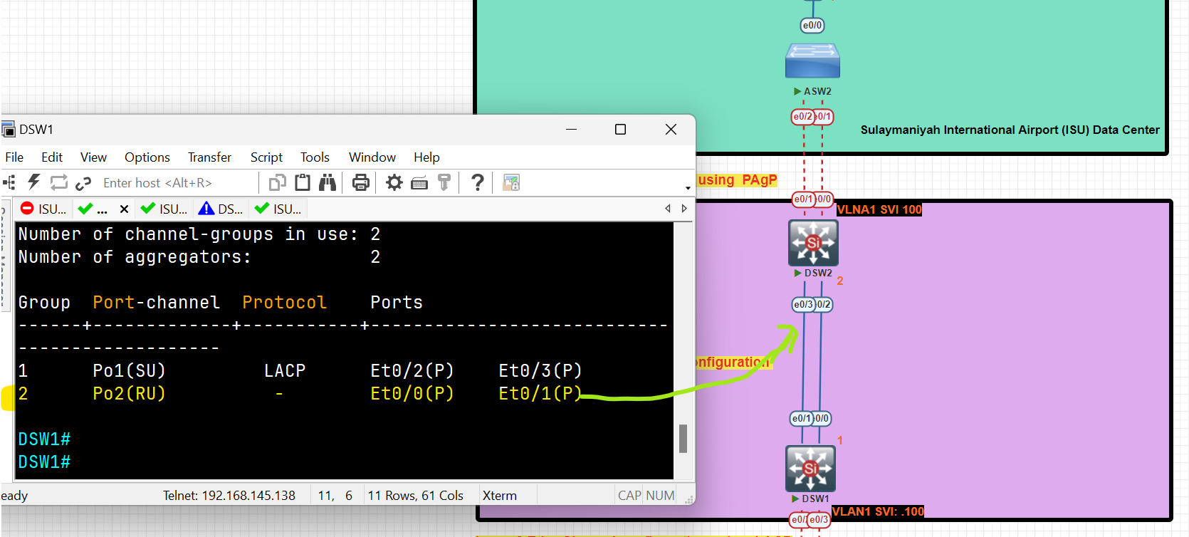
EtherChannel layer 3 has been established between two layer 3 switches.
Configure a static route to reach the IT Department pc to the Server in the Data Center
DSW1(config)#ip routing
DSW1(config)#ip route 172.16.1.0 255.255.255.0 10.0.0.2
DSW2(config)#ip routing
DSW2(config)#ip route 172.16.2.0 255.255.255.0 10.0.0.1
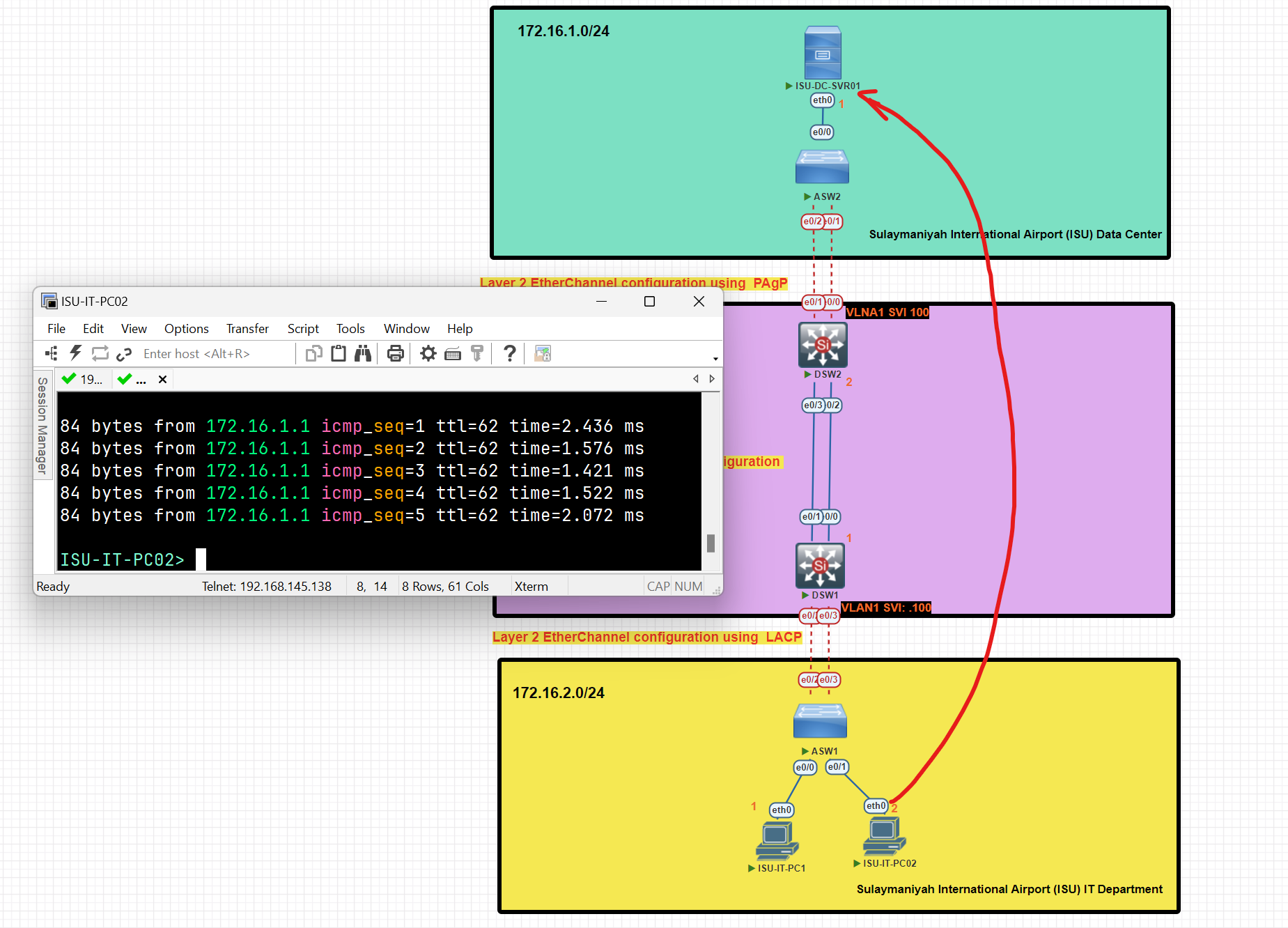
After completing the configuration, clients from the IT department have established a connection with the server located in the data center.
Notes:
- Channel-Group should be unique and not repeated on the same switch.
- PO= port-channel.
- Before starting the configuration of channel groups, make sure all interfaces are down.
Question #: 1266
Question #: 1339
Routing
What is a Router?
- A router is a layer 3 device used for interconnecting networks at layer 3**.**
- Routing is the process of identifying the best path to a destination.
- Routers make their forwarding decision based on Layer 3 (IP Address), unlike Switches, which make their decision based on Layer 2 ( MAC Address).
- Generally, a router has at least two interfaces, but with the use of VLANs, it can have only one interface.
- The router receives the message, de-encapsulates the Ethernet frame, and then reads the destination IP address (Network portion) in the IP packet. It then determines where to forward the message. It re-encapsulates the packet back into a new frame and forwards the frame to its destination.
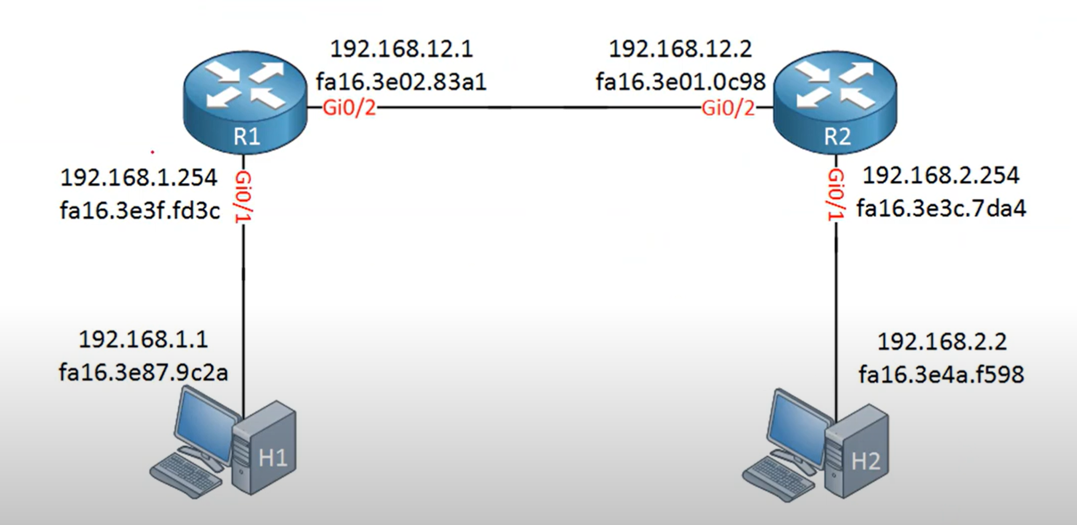
The Routing Table
- A routing table is a data structure used by routers and networked devices (like servers, PCs, and switches with Layer 3 capabilities) to determine the best path for forwarding packets to their destinations.
- Routing table updates are done in two ways:
- Dynamically: Remote routes are automatically learned using a dynamic routing protocol.
- Manually: Remote networks are manually entered into the route table using static routes.
- If the router can't determine where to forward a message, it will drop it. The Network Administrator configures a static default route that is placed into the routing table so that a packet will not be dropped due to the destination network not being in the routing table.
Directly connected: means that the router is connected to the network directly.
Default Gateway
A default gateway is the router IP address on your local network that your device uses to send traffic outside of its subnet.
Think of it as the “exit door” from your local network to other networks (like the internet).
💡 Hosts with an incorrect default gateway can communicate with other hosts on a local network, but can’t communicate with hosts in other networks.
What is the purpose of ARP in an IPv4 network?
- to obtain a specific MAC address when an IP address is known.
The ARP table in a switch maps which two types of addresses together?
- Layer 3 address to a Layer 2 address
What does the router do after it determines that a data packet from Network 1 should be forwarded to Network 2?
- It reassembles the frame with MAC addresses different from the original frame.
A host needs to reach another host on a remote network, but the ARP cache has no mapping entries. To what destination address will the host send an ARP request?
- the broadcast MAC address
When we configure an IP address on an Interface and enable the interface, two routes are automatically added to the routing table:
- Connected Route C (Code C in the routing table): represents a network directly attached to the router interface,
- Local Route L (Code L in the Routing table) represents the IP address assigned and configured to the router's specific interface and is always a /32 (host route).
Router VS L3 Switch
| Attribute | Layer 3 switch | Router |
| Scope | LAN for office, data center, and campus environment | WAN For office,Datacenter and campus environment |
| Key functionality | Routes across different subnets or VLANs on a campus LAN | Routes across different networks across WAN are communicated and routed by a router. |
| Edge technologies support | Not supporting | NAT, Firewalling, tunneling, IPsec |
| Size of routing tabel | Smaller routing table compared to router | Bigger to support multiple route entries |
| Interface support | Ethernet ports(copper/fiber) | Ethernet ports(copper/fiber), interface like SONT, OC-N, T1/T3 etc |
| Throughput | High Throughput (because of large amount ports) | Low than layer 3 switches (because of less amount ports) |
| Switching capacity | High switching capacity | Lower than layer 3 switches |
| Cost | Low cost | High cost |
| Port Density | High | Low |
The port density of a switch refers to the number of ports available on a single switch.
Type of Routing
Static Routing
Static routes are mainly configured when routing from a particular network to a stub network.
Router(config)# ip route 192.168.3.0 255.255.255.0 [next-hop ip address or exit interface]
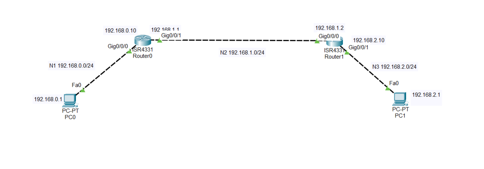
Default Route (gateway of last resort)
A gateway of Last Resort is a route that a router uses when it does not have a more specific match for a destination in its routing table. It is essentially the default route, directing traffic to a next-hop router when no other routes match.
Router(config)# ip route 0.0.0.0 0.0.0.0 [next-hop ip address or exit interface]
Gateway of last resort is 192.168.1.1 to network 0.0.0.0
Gateway of last resort is 192.168.1.1 to network 0.0.0.0

     10.10.10.0/24 is directly connected, Gig0/0
     172.16.0.0/16 is directly connected, Gig0/1
     0.0.0.0/0 [1/0] via 192.168.1.1
- The router knows about
10.10.10.0/24and172.16.0.0/16. - If traffic is going to, say,
8.8.8.8(Google DNS), It doesn’t match any specific route. - So the router sends it to the gateway of last resort:
192.168.1.1.
Static Route
Advantage:
- No routing overhead for the router CPU, which means a cheaper router can be used to do routing.
- It adds security because only the administrator can allow routing to particular networks.
- No bandwidth usage between routes, and any updating did not happen between routes, such as dynamic routing)
Disadvantage:
- For a large network, it is hectic for the administrator to manually add each route for the network in the routing table on each router.
- The administrator should have good knowledge of the topology. If a new administrator comes, then he has to manually add each route, so he should have a very good knowledge of the router topology.
Static Route Lab
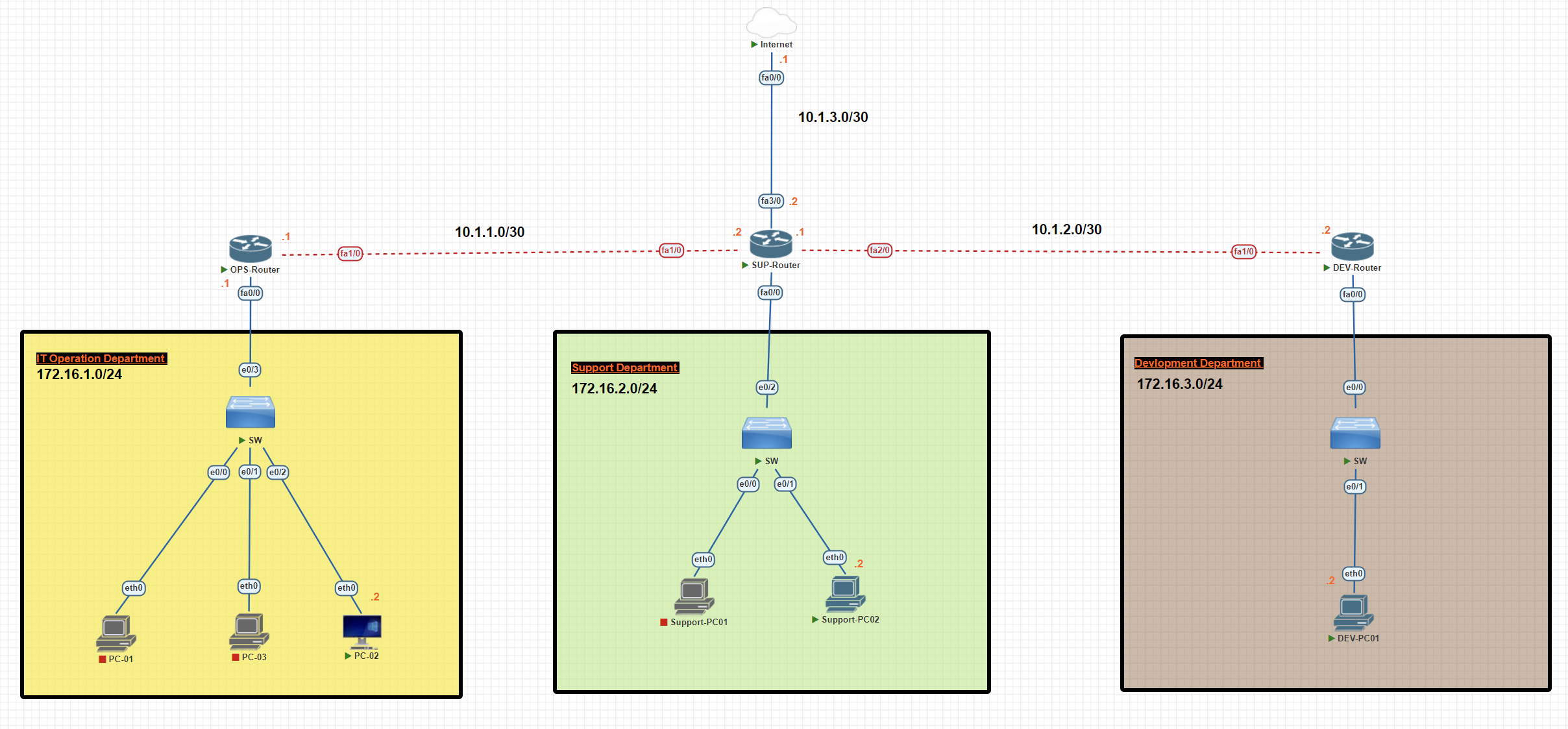
In this scenario, we have three departments, each with a unique subnet. We will establish a connection between the departments through static routing and forward unknown destinations to the internet.
Operation Router Configuration
OPS-Router#conf t
OPS-Router(config)#int fa0/0
OPS-Router(config-if)#ip add 172.16.1.1 255.255.255.0
OPS-Router(config-if)#no shutdown
OPS-Router(config-if)#exit
SUP-Router#conf t
OPS-Router(config)#int fa1/0
OPS-Router(config-if)#ip add 10.1.1.1 255.255.255.252
OPS-Router(config-if)#no shutdown
Support Router Configuration
SUP-Router#conf t
SUP-Router(config)#int fa1/0
SUP-Router(config-if)#ip add 10.1.1.2 255.255.255.252
SUP-Router(config-if)#no shutdown
SUP-Router(config-if)#exit


SUP-Router(config)#int fa2/0
SUP-Router(config-if)#ip add 10.1.2.1 255.255.255.252
SUP-Router(config-if)#no shutdown


SUP-Router(config)#int fa0/0
SUP-Router(config-if)#ip add 172.16.2.1 255.255.255.0
SUP-Router(config-if)#no shutdown


SUP-Router(config)#int fa3/0
SUP-Router(config-if)#ip address 10.1.3.2 255.255.255.252
SUP-Router(config-if)#no shutdown
Development Router Configuration
DEV-Router#conf t
DEV-Router(config)#int fa1/0
DEV-Router(config-if)#ip address 10.1.2.2 255.255.255.252
DEV-Router(config-if)#no shutdown
DEV-Router(config-if)#exit

DEV-Router(config)#int fa0/0
DEV-Router(config-if)#ip add 172.16.3.1 255.255.255.0
EV-Router(config-if)#no shutdown
Internet Router Configuration
Internet#conf t
Internet(config)#int fa 0/0
Internet(config-if)#ip address 10.1.3.1 255.255.255.252
Internet(config-if)#no shutdown
Internet#wr
PC Configuration Operation Department
PC-02> ip 172.16.1.2 255.255.255.0 172.16.1.1
PC Configuration Support Department
Support-PC02> ip 172.16.2.2 255.255.255.0 172.16.2.1
PC Configuration Development Department
DEV-PC01> ip 172.16.3.2 255.255.255.0 172.16.3.1
Operation Router Static Route Configuration
OPS-Router#conf t
OPS-Router(config)#ip route 172.16.2.0 255.255.255.0 10.1.1.2
OPS-Router(config)#ip route 172.16.3.0 255.255.255.0 10.1.1.2
OPS-Router(config)#ip route 0.0.0.0 0.0.0.0 10.1.1.2
OPS-Router(config)#exit
OPS-Router#wr
OPS-Router#show ip route static
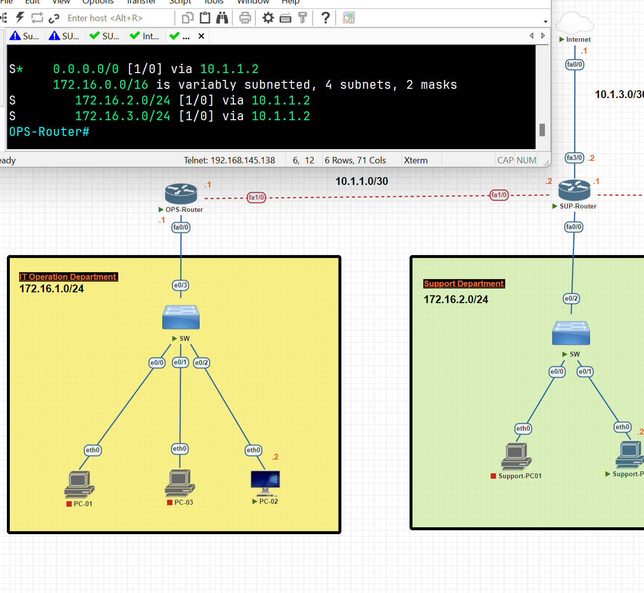
Support Router Static Route Configuration
SUP-Router#conf t
SUP-Router(config)#ip route 172.16.1.0 255.255.255.0 10.1.1.1
SUP-Router(config)#ip route 172.16.3.0 255.255.255.0 10.1.2.2
SUP-Router(config)#ip route 0.0.0.0 0.0.0.0 10.1.3.1
SUP-Router(config)#exit
SUP-Router#wr
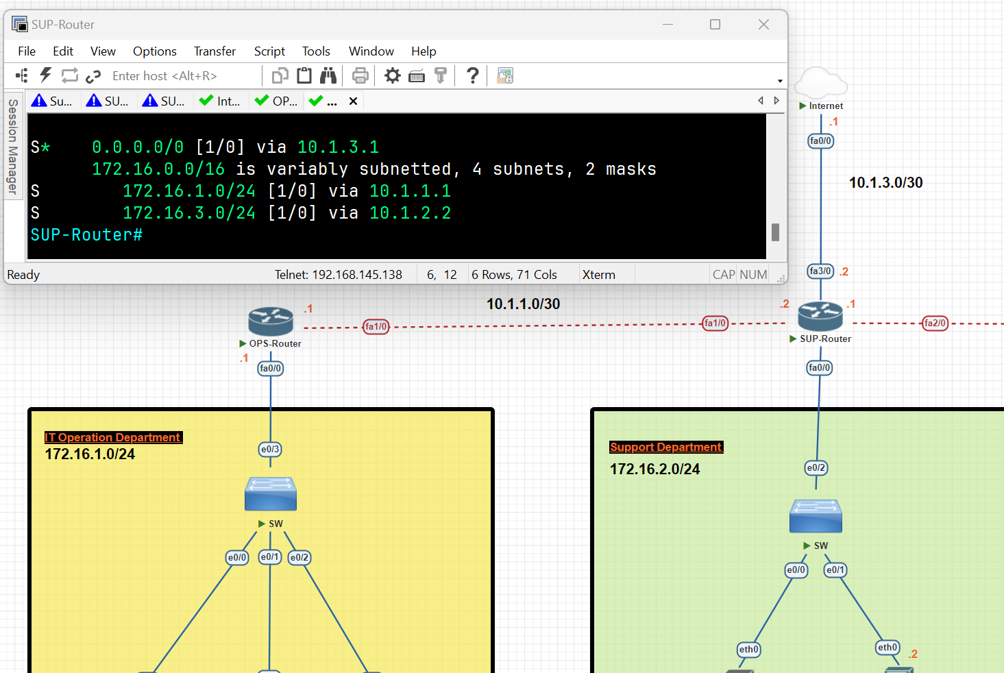
DEV-Router#conf t
DEV-Router(config)#ip route 172.16.1.0 255.255.255.0 10.1.2.1
DEV-Router(config)#ip route 172.16.2.0 255.255.255.0 10.1.2.1
DEV-Router(config)#ip route 0.0.0.0 0.0.0.0 10.1.2.1
DEV-Router(config)#exit
DEV-Router#wr
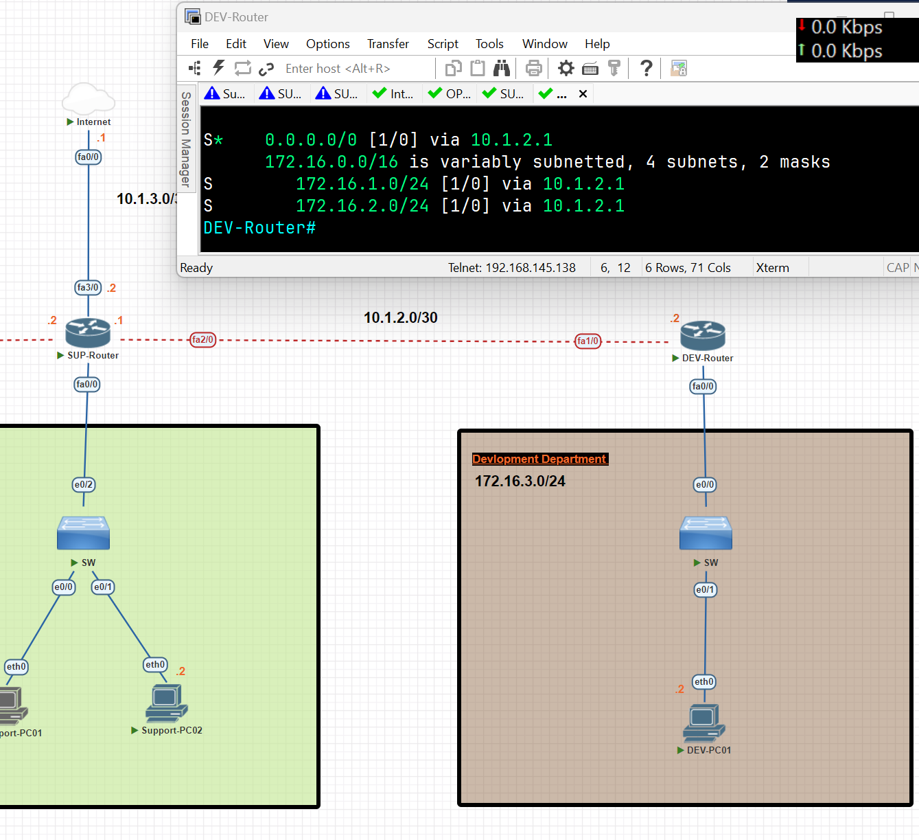
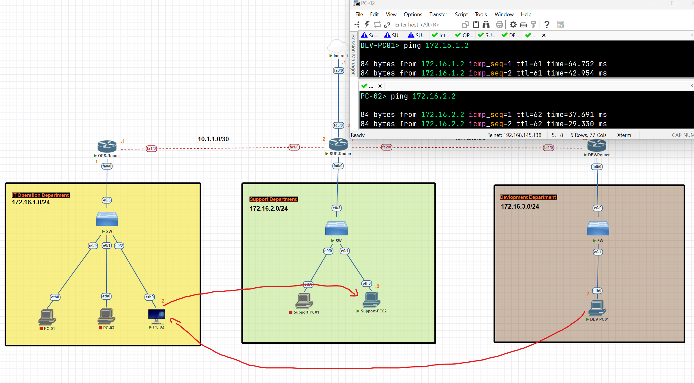
Now, as you can see, the connection between departments has been established.
Dynamic Routing
- Dynamic routing makes automatic adjustments to the routes according to the current state of the route in the routing table. Dynamic routing uses protocols to discover network destinations and the routes to reach them.
Dynamic protocols have the following features:
- The routers should have the same dynamic protocol running in order to exchange routes.
- When a router finds a change in the topology, the router broadcasts it to all other routers.
Advantages:
- Easy to configure
- More effective at selecting the best route to the destination remote network and also for discovering remote networks.
Disadvantage:
- Consumes more bandwidth for communication with other neighbours.
- Less secure than static routing. (because we decided in which path the data should be transferred).
Dynamic Routing Protocols:
- Routing Protocols: Help routers add information to their routing tables from connected routers automatically. These types of protocols also send out topology updates whenever changes happen in the topology.
Type of Routing Protocols
- Distance Victor or Link state protocols.
- Interior Gateway Protocols (IGP) or Exterior Gateway Protocols (EGP).
- Classful or Classless Protocols. (old not useful, classful can not be subnetted)
Type of Routing Protocols
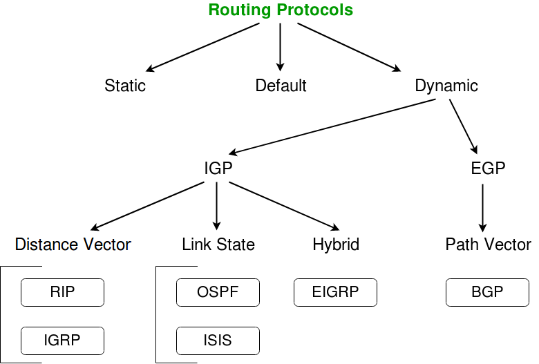
- IGP (Interior Gateway Protocol): Used for routing inside a single organization or network (Autonomous System). It helps routers within the same network share routes. Examples: OSPF, EIGRP, RIP, and IS-IS.
- EGP (Exterior Gateway Protocol): Used for routing between different organizations or networks (Autonomous Systems). It helps networks on the internet share routes. The main example today is BGP (Border Gateway Protocol).
Distance Vector Routing Protocol
- Distance Vector Protocol broadcasts its routing table to every directly connected neighbour at specific time intervals, using a lot of bandwidth and slow convergence**.** In the Distance Vector Routing protocol, when a route becomes unavailable, all router tables need to be updated with new information.
Distance Vector Protocols work best in these situations:
- When the network is simple and flat, and doesn’t require a hierarchical design.
- When the administrators don’t have enough knowledge to configure and troubleshoot link-state protocols.
- When worst-case convergence times in a network are not a concern. (that the speed at which the network protocols adjust to changes, such as topology updates, link failures, or new configurations, is not critical to the network's operation or performance requirements)
Link State Protocols
- Link State protocols find the best routing path by sharing information with other routes in proximity. The route is calculated based on the speed of the path to the destination and the cost of resources.
- One key difference to a distance vector protocol is that link state protocols don’t send out routing tables instead, routes notify each other quickly when route changes are detected.
- Link State protocols use more resources (CPU) on the router because more information is shared.
Link-State works best in these situations:
- When the network design is hierarchical.
- When the administrators have good knowledge of the implemented link-state routing protocol.
- When the fast convergence of the network is crucial.
| Distance Vector | Link State |
| Distance Vector Protocol sends the entire routing table. | Link State Protocol sends only link-state information |
| It is allowing to routing loops | it is less allowing to routing loops |
| Updates sometimes sent using broadcast | Uses only multicast method for routing updates. |
| It is simple to configure | It is hard to configure |
| Doesn’t know network topology | Know the entire topology |
| Example: Rip, IGRP | Example: OSPF, IS-IS |
| RIP | Routing Information Protocol |
| IGRP | Interior Gateway Routing Protocol |
| OSPF | Open Shortest Path First |
| ISIS | Intermediate System to Intermediate System. |
| EIGRP | Enhanced Interior Gateway Routing Protocol |
| BGP | Border Gateway Protocol |
| Routing protocol | Metric | Description |
| RIPv1,2 | Hop count | The number of routers between the source and destination network. |
| EIGRP | Matric based on bandwidth and delay (by default | A combination of several values used to determine the best path. The composite metric will be discussed in the chapter on EIGRP. |
| OSPFv2 | Cost | The cost of each link is calculated based on bandwidth. |
The total matric is the total cost of each link in the route. | | IS-IS | Cost | The total metric is the total cost of each link in the route. the cost of each link is not automatically calculated by default. All Links have a cost 10 by default. |
Administrative Distance
Routers use this feature to select the best path when there are two or more routes to the same destination using different routing protocols. Administrative distance defines the reliability of the routing protocol.
Lower AD is Preferred: The route with the lowest AD value is selected.
Static Value: Assigned by default but can be adjusted manually.
| Directly connected | 0 |
| Static | 1 |
| External BGP | 20 |
| EIGRP | 90 |
| IGRP | 100 |
| OSPF | 110 |
| IS-IS | 115 |
| RIP | 120 |
| EIGRP(External) | 170 |
| Internal BGP | 200 |
Metrics
A metric is a value that routing protocols use to determine the best path to a destination network. When multiple routes exist with the same routing protocol, the router chooses the path with the lowest metric because it is considered the most efficient.
- The following routes to the destination network 10.1.1.0/24 are learned:
- next hop 192.168.1.1, learned via RIP, metric 5
- next hop 192.168.2.1, learned via RIP, metric 3
- next hop 192.168.3.1, learned via OSPF, metric 10
Which route to 10.1.1.0/24 will be added to the route table?
next hop 192.168.3.1, learned via OSPF, metric 10
💡 We don't consider the metric directly because the routes are learned from different routing protocols. Each protocol has its own Administrative Distance (AD), and this value is used to select the best route. OSPF typically has a lower AD, making its routes more preferred
How to check the Administrative Distance and Metric of each Route
R1#show ip route
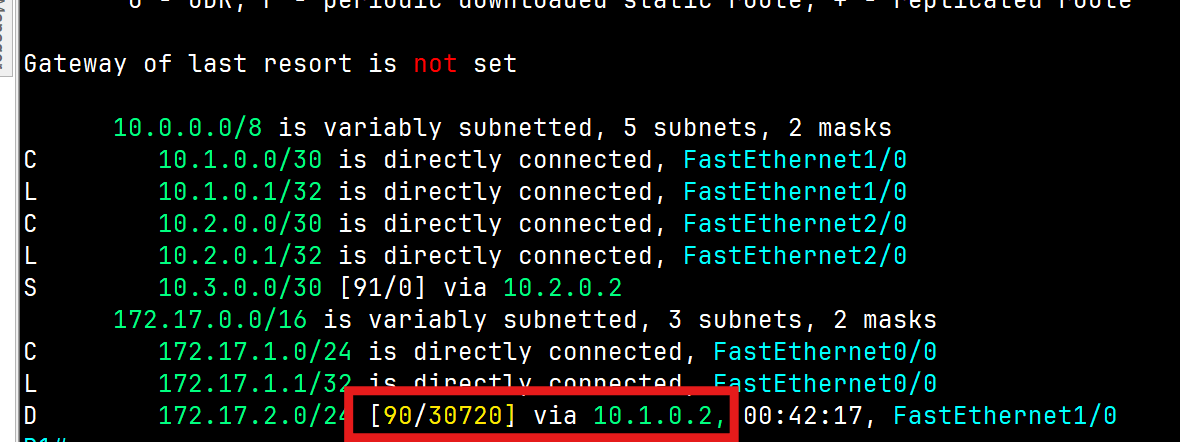
Administrative Distance = 90 Metric=30720
Autonomous System
An Autonomous System (AS) is a set of Internet-routable IP prefixes belonging to a network or a collection of networks that are all managed, controlled, and supervised by a single entity or organization. The AS is assigned a globally unique 16-digit identification number一known as the autonomous system number or ASN一by th e Internet Assigned Numbers Authority (IANA).

Routing Information Protocol (RIP)
- Routing Information Protocol(RIP): This is one of the first routing protocols to be created. There are multiple versions of RIP, including RIPv1 and RIPv2. The original version, RIPv1, determines network paths based on the IP destination and hop count of the journey and uses the broadcast address.
- RIPv2 is a little more sophisticated than this and sends its routing table to a multicast address. RIPv2 also uses authentication to keep data more secure and choose a subnet mask and gateway for future traffic. The main limitation of RIP is that it has a maximum hop count of 15, which makes it unsuitable for a large network.
- RIPng(RIP Next Generation), used for IPv6
- It uses two messages every 30 seconds: Request: To ask RIP-enabled neighbour routers to send their routing table. Response: To send the local router’s routing table to neighbouring routers
RIP&EIGRP Lab
In this scenario, we will be establishing dynamic routing between Network 1 in North Erbil and Network 2 in South Erbil using the RIP protocol.
Network 1 Basic IP Configuration
PC IP Address
VPC> ip 172.16.1.2 255.255.255.0 172.16.1.1
Router R1 IP configuration
R1#conf t
R1(config)#int fa 1/0
R1(config-if)#ip address 172.16.1.1 255.255.255.0
R1(config-if)#no shutdown
R1(config-if)#exit

R1(config)#int fa0/0
R1(config-if)#ip add 10.0.0.1 255.255.255.0
R1(config-if)#no shutdown
R1(config-if)#exit
R1(config)#exit
R1#wr
Network 2 Basic IP Configuration
PC IP Address
VPC> ip 172.16.2.2 255.255.255.0 172.16.2.1
Router R1 IP configuration
R2#conf t
R2(config)#int fa1/0
R2(config-if)#ip add 172.16.2.1 255.255.255.0
R2(config-if)#no shutdown
R2(config-if)#exit

R2(config)#int fa 0/0
R2(config-if)#ip add 10.0.0.2 255.255.255.0
R2(config-if)#no shutdown
R2(config-if)#exit
R2(config)#exit
R2#wr
RIP (Routing Information Protocol) Configuration
RIP Protocol Configuration Network 1
R1(config)#router rip
R1(config-router)#version 2
R1(config-router)#no auto-summary
R1(config-router)#network 10.0.0.0
R1(config-router)#network 172.16.1.0
R1(config-router)#passive-interface fa1/0 [prevent the router from sending routing table to the mentioned interface]
R1(config-router)#exit
R1(config)#exit
R1#wr
RIP Protocol Configuration Network 2
R2(config)#router  rip
R2(config-router)#version 2
R2(config-router)#no auto-summary
R2(config-router)#network 10.0.0.0
R2(config-router)#network 172.16.2.0
R2(config-router)#passive-interface fa1/0
R2(config-router)#exit
R2(config)#exit
R2#wr
RIP Routing Verification
R1#show ip route rip
R1#debug ip rip
As you can see each router exchanges the routing table with neighbours, routing table entries are not advertised on interfaces connected to end devices. This is a key benefit of using the 'passive-interface' command in routing protocols.
R1#show ip protocols
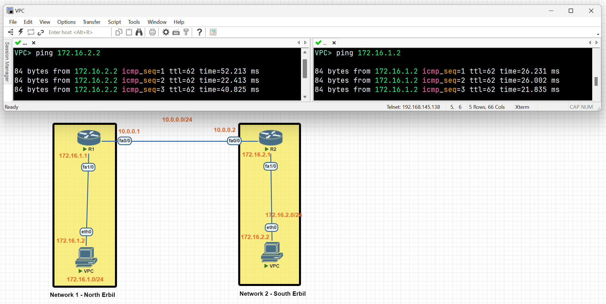
It can be seen that a connection between network 1 and network 2 has been established using the RIP protocol.
EIGRP
- Enhanced Interior Gateway Routing Protocol (EIGRP) is an advanced distance vector routing protocol. EIGRP was a Cisco proprietary (till 2013) protocol that was designed to follow the original IGRP protocol. When using EIGRP, a router takes information from its neighbours’ routing tables through a multicast message.
EIGRP LAB
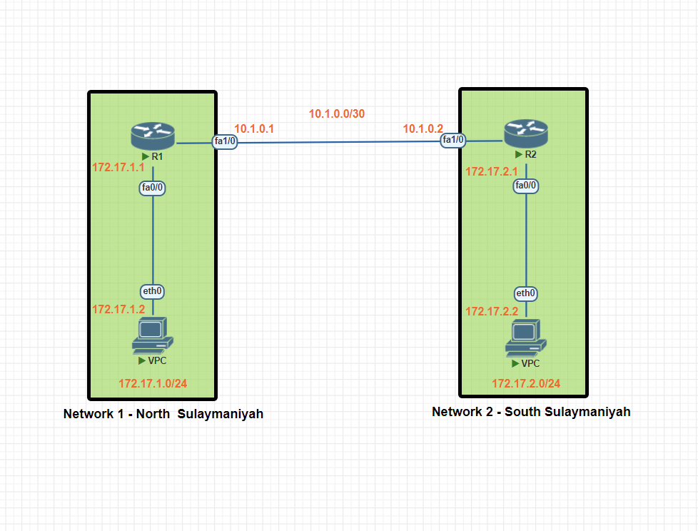
In this scenario, we will be establishing dynamic routing between Network 1 in North Sulaymaniyah and Network 2 in South Sulaymaniyah using the EIGRP protocol.
Network 1 Basic IP Configuration
PC IP Address
VPC> ip 172.17.1.2 255.255.255.0 172.17.1
Router R1 IP configuration
R1#conf t
R1(config)#int fa0/0
R1(config-if)#ip add 172.17.1.1 255.255.255.0
R1(config-if)#no shut
R1(config-if)#exit


R1(config)#int fa1/0
R1(config-if)#ip add 10.1.0.1 255.255.255.252
R1(config-if)#no shutdown
R1(config-if)#exit
R1(config)#exit
R1#wr
Network 2 Basic IP Configuration
PC IP Address
VPC> ip 172.17.2.2 255.255.255.0 172.17.2.1
Router R2 IP configuration
R2#conf t
R2(config)#int fa1/0
R2(config-if)#ip add 10.1.0.2 255.255.255.252
R2(config-if)#no shutdown
R2(config-if)#exit

R2(config)#int fa 0/0
R2(config-if)#ip add 172.17.2.1 255.255.255.0
R2(config-if)#no shutdown
R2(config-if)#exit
R2(config)#exit
R2#wr
EIGRP(Enhanced Interior Gateway Routing Protocol) Configuration
EIGRP Protocol Configuration Network 1
R1(config)#router eigrp 100 (<u>**Autonomous Systems (AS) ID**</u> )
R1(config-router)#network 10.1.0.0 0.0.0.3 ip wildcard (255.255.255.252 = 0.0.0.3 [255-252])
R1(config-router)#network 172.17.1.0 0.0.0.255
R1(config-router)#no auto-summary
R1(config-router)#exit
R1(config)#exit
R1#wr
Note:
- All routers within an Autonomous System (AS) should have the same AS number, which is considered a unique identifier for a network.
- Auto-summary: This feature automatically summarizes routes to their classful network boundaries. For example, a network with a /26 or /27 prefix would be summarized as a /24. This can lead to subnetting issues and is generally not recommended for most modern networks.
EIGRP Protocol Configuration Network 2
R2(config)#router eigrp 100
R2(config-router)#network 10.1.0.0 0.0.0.3
R2(config-router)#network 10.1.0.0 0.0
R2(config-router)#no auto-summary
R2(config-router)#exit
R2(config)#exit
R2#wr
EIGRP Routing Verification
R1#show ip route eigrp
R1#show ip protocols
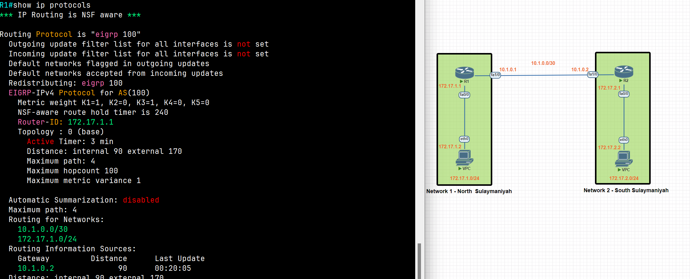
R1#show ip eigrp neighbors
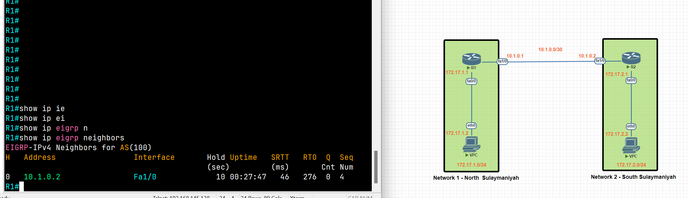
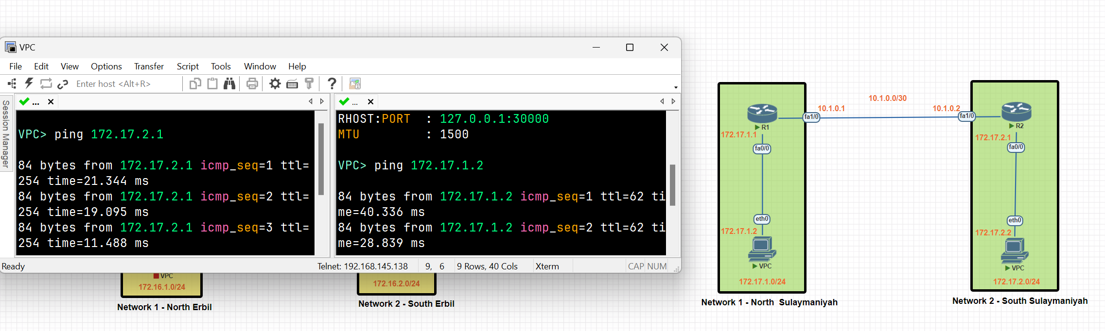
A connection between Network 1 and Network 2 has been established using the EIGRP protocol.
Floating Static Route
Static routes have a very low distance value of 1. This means the router will prefer a static route over any routes learned through a dynamic routing protocol. If we want to use a static route as a backup route, we should change the administrative distance value of the static route. This is called a floating static route.
Floating Static Route
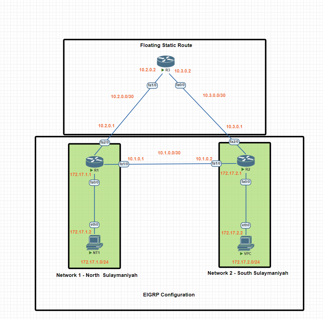
In this scenario, we will be establishing dynamic routing between Network 1 in North Sulaymaniyah and Network 2 in South Sulaymaniyah using the EIGRP protocol. A floating static route will be configured as a backup, ensuring network connectivity even if the EIGRP protocol encounters issues.
Network 1 Basic IP Configuration
PC IP Address
VPC> ip 172.17.1.2 255.255.255.0 172.17.1
Router R1 IP configuration
R1#conf t
R1(config)#int fa0/0
R1(config-if)#ip add 172.17.1.1 255.255.255.0
R1(config-if)#no shut
R1(config-if)#exit

R1(config)#int fa 2/0
R1(config-if)#ip add 10.2.0.1 255.255.255.252
R1(config-if)#no shut
R1(config-if)#exit
R1(config)#exit

R1(config)#int fa1/0
R1(config-if)#ip add 10.1.0.1 255.255.255.252
R1(config-if)#no shutdown
R1(config-if)#exit
R1(config)#exit
R1#wr
Network 2 Basic IP Configuration
PC IP Address
VPC> ip 172.17.2.2 255.255.255.0 172.17.2.1
Router R2 IP configuration
R2#conf t
R2(config)#int fa1/0
R2(config-if)#ip add 10.1.0.2 255.255.255.252
R2(config-if)#no shutdown
R2(config-if)#exit

R2(config)#int fa 0/0
R2(config-if)#ip add 172.17.2.1 255.255.255.0
R2(config-if)#no shutdown
R2(config-if)#exit
R2(config)#exit

R2(config)#int fa2/0
R2(config-if)#ip add 10.3.0.1 255.255.255.252
R2(config-if)#no shu
R2(config-if)#no shutdown

R2(config-if)#exit
R2(config)#exit
R2#wr
Router R3 IP configuration
R3#conf t
R3(config)#int fa1/0
R3(config-if)#ip add 10.2.0.2 255.255.255.252
R3(config-if)#no shut


R3(config-if)#exit
R3(config)#int fa0/0
R3(config-if)#ip add 10.3.0.2 255.255.255.252
R3(config-if)#no shut

R3(config-if)#exit
R3(config)#exit
R3#wr
Static Routing Configuration
R1(config)#ip route 172.17.2.0 255.255.255.0 10.2.0.2
R1(config)#ip route 10.3.0.0 255.255.255.252 10.2.0.2


R3(config)#ip route 172.17.2.0 255.255.255.0 10.3.0.1
R3(config)#ip route 172.17.2.0 255.255.255.0 10.3.0.1


 R2(config)#ip route  172.17.1.0 255.255.255.0 10.3.0.2
 R2(config)#ip route  10.2.0.0  255.255.255.252  10.3.0.2
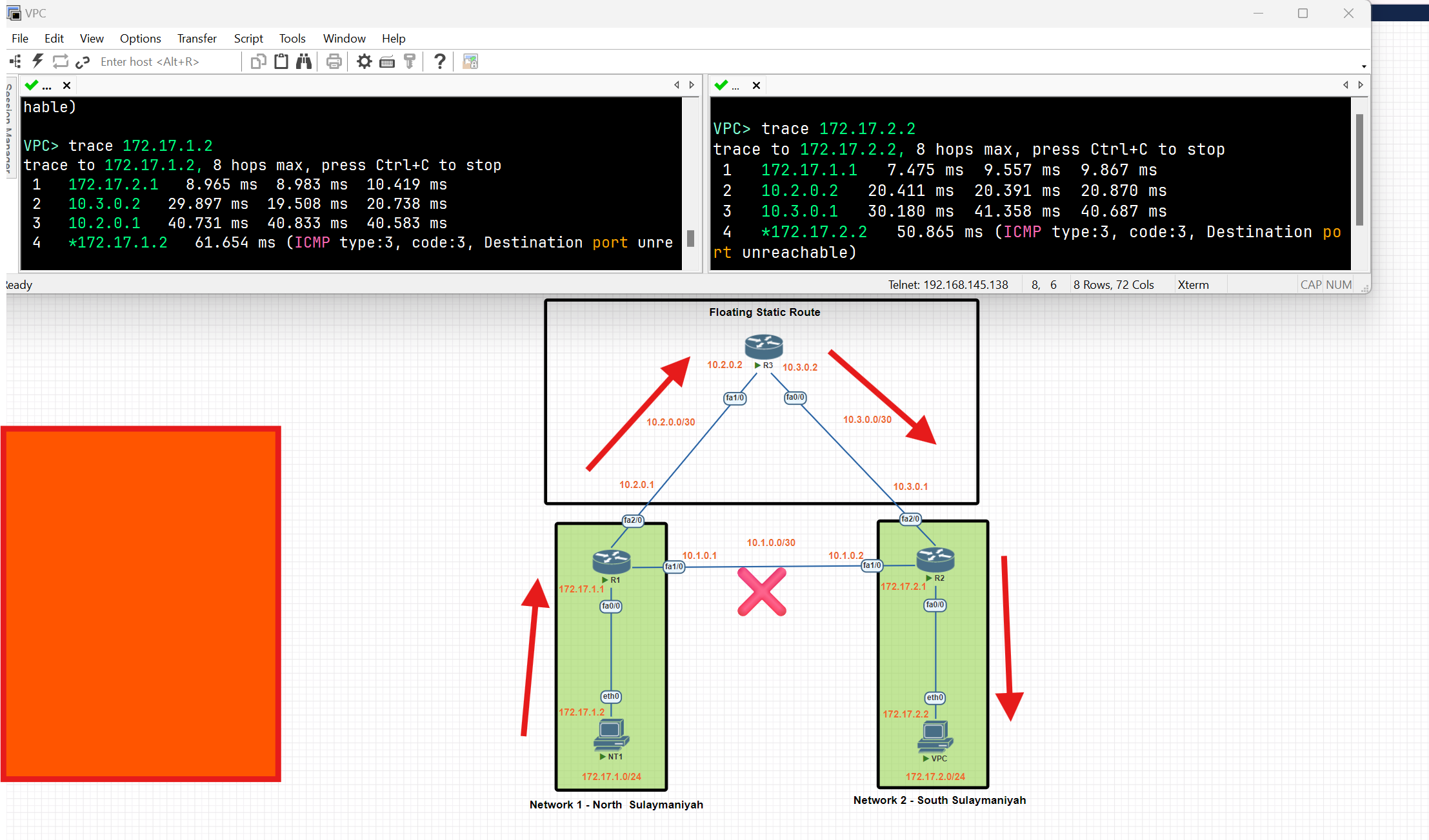
After configuring the static route, data is forwarded through the static route because of the low administrative distance value.
Configure Floating Static Route
Our network topology is configured with EIRGP, and the default distance value of EIRGP is 90 our static route will be used as a backup. Let’s set the distance value to 91.
R1(config)#ip route 172.17.2.0 255.255.255.0 10.2.0.2 91
R1(config)#ip route 10.3.0.0 255.255.255.252 10.2.0.2  91


 R3(config)#ip route 172.17.2.0 255.255.255.0 10.3.0.1 91
 R3(config)#ip route 172.17.2.0 255.255.255.0 10.3.0.1  91


  R2(config)#ip route  172.17.1.0 255.255.255.0 10.3.0.2  91
  R2(config)#ip route  10.2.0.0  255.255.255.252  10.3.0.2 91
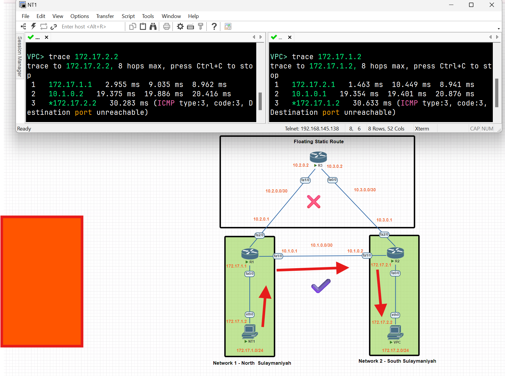
After configuring a floating static route, the routers in Network 1 and Network 2 utilize the EIGRP to route data between each other, and the static route works as a backup.
OSPF
- Open Shortest Path First (OSPF) is a link-state routing protocol that is used to find the best path between the source and the destination router using its own Shortest Path First.
- The protocol recalculates routes when a link fails and the network topology changes, Using the Dijkstra(dike·struh) algorithm, and minimizes the routing protocol traffic that it generates.
- It provides a multi-level hierarchy called “area routing” so that information about the topology within the defined area of the AS is hidden from routes outside this area. This enables an additional level of routing protection and reduction in routing protocol traffic.
- All protocol exchanges can be authenticated so that only trusted routers can join in the routing exchanges for the AS
Benefits of OSPF:
- Fast convergence.
- Efficient use of network resources.
- Support for large, complex networks.
- Ability to route IPv4 and IPv6 traffic (OSPFv2 for IPv4, OSPFv3 for IPv6).
- Redundancy and fault tolerance.
- VLSM (Classless Routing) and route summarization
OSPF Concepts
Area
- An area is a logical collection of OSPF networks, routers, and links that have the same area identification.
- The most important area in OSPF is the backbone area, also known as area 0. The backbone area is the central area that interconnects all other areas.
- In a large network, a single-area design can have negative effects:
- The SFP algorithm takes more time to calculate routes and it causes the algorithm to require more processing power.
- Any small change in the network causes every router to flood LSAs and run the SPF algorithm again.
- By dividing a large OSPF network into several smaller areas, you can avoid the above negative effects.
Neighbour
- Routers running OSPF need to establish a neighbour relationship before exchanging routing updates. Neighbours are dynamically discovered by sending Hello packets out of each OSPF-enabled interface.
Hello Packets:
OSPF uses multicast addresses to communicate and exchange Hello Packets between routers
- 224.0.0.5: All OSPF routers.
- 224.0.0.6: All OSPF designated routers (DRs) and backup designated routers (BDRs).
- Hello Interval:
- The OSPF router sends a hello message on an interface. It is 10 seconds by default.
- Dead Interval:
- The Dead interval is four times the Hello interval, which means a Dead interval of 40 seconds
- If a router does not receive at least one Hello packet from a neighbour within the Dead interval, the neighbour is considered down.
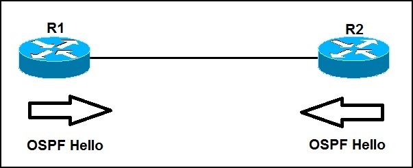
ABR and ASBR
- Area Border Router(**ABR**): a router that connects two or more OSPF areas, one of which must be the backbone area (area 0).
- Autonomous System Boundary Router(**ASBR**) is a router that connects two different Autonomous Systems (AS) and helps them communicate with each other. It usually runs BGP (Border Gateway Protocol) to exchange routing information between the AS, while OSPF is used within an AS. It is responsible for importing and redistributing routes from non-OSPF sources into the OSPF routing source.
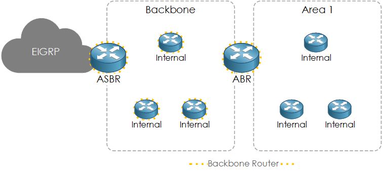
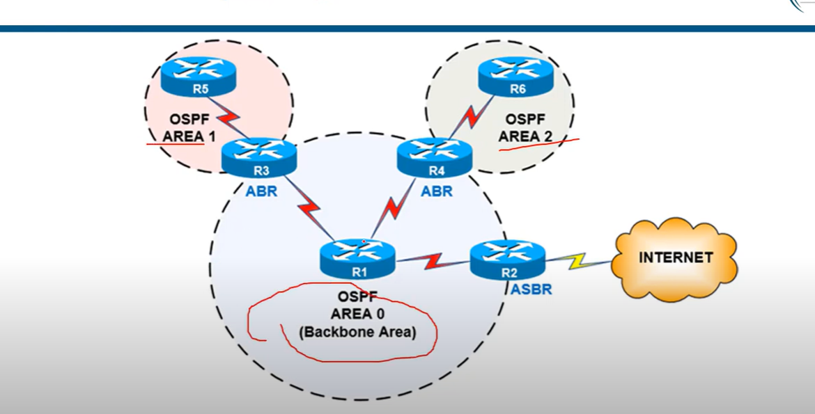
Designated Router and Backup Designated Router
- Designated Router (**DR) and Backup Designated Router(BDR**) are to act as a central point for exchanging OSPF information between multiple routers on the same network. Each non-DR and non-BDR router only exchanges routing information with the DR and BDR, instead of exchanging updates with every router on the segment. This significantly reduces the amount of OSPF updates sent across the network.
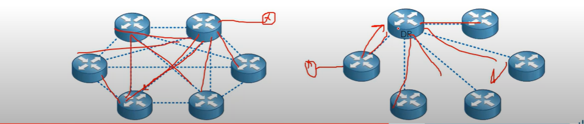
DR and BDR Election
OSPF uses the following tie-breaker order:
1- Interface priority (0–255, default = 1; if set to 0, the router never becomes DR/BDR).
R1(config)#interface fastEthernet 0/0
R1(config-if)#ip ospf priority 200
2- Highest router ID is a 32-bit number that uniquely identifies every OSPF router.
R1# conf t
R1#(config) router ospf 100(OSPF process number).
R1#(config-router)# router-id 1.1.1.1
3- Highest IP address on a loopback address (first check loopback if no loopback IP configuration, then check physical interface IP) or an active physical interface.
💡 - OSPF Router ID should not be changed after the OSPF process has started and the OSPF neighborships have been established. If you change the OSPF Router ID, we need to either reload the IOS or use the command (
clear ip ospf process), for the OSPF Router ID change to take effect. Reloading the IOS or using the command [clear ip ospf process] can cause a temporary network outage.
- OSPF Router ID should not be changed after the OSPF process has started and the OSPF neighborships have been established. If you change the OSPF Router ID, we need to either reload the IOS or use the command (
clear ip ospf process), for the OSPF Router ID change to take effect. Reloading the IOS or using the command [clear ip ospf process] can cause a temporary network outage.
💡 Best Practice (What Network Engineers Prefer)
Use interface priority to control DR/BDR election.
Set the router you want as DR with a higher priority (e.g., 100).
Set critical backups as BDR with a slightly lower priority.
Set devices that should never be DR (like access switches or less powerful routers) to priority 0.
Use interface priority to control DR/BDR election.
- Set the router you want as DR with a higher priority (e.g., 100).
- Set critical backups as BDR with a slightly lower priority.
- Set devices that should never be DR (like access switches or less powerful routers) to priority 0.
Loopback Interface Configuration
R1#conf t
R1(config)#interface loopback 0
R1(config-if)#ip address 10.0.0.1 255.255.255.0
R1(config-if)#exit
OSPF Process ID
- The process ID is the ID of the OSPF process to which the interface belongs. The process ID is local to the router, and two OSPF neighbouring routers can have different OSPF process IDs. (Not like EIGRP). Cisco IOS software can run multiple OSPF processes on the same router**, The Router ID should be a positive integer; for example, the process ID is 1**
## Link State Advertisement (LSAs)
- Link-State Advertisement (LSA) is a packet used to share routing and topology information between routers within the same area. LSAs help OSPF routers build a complete map of the network.
| LSA Type 1: | Router LSA |
| LSA Type 2: | Network LSA |
| LSA Type 3: | Summary LSA |
| LSA Type 4: | Summary ASBR LSA |
| LSA Type 5: | Autonomous system external LSA |
| LSA Type 6: | Multicast OSPF LSA |
| LSA Type 7: | Not-so-stubby area LSA |
| LSA Type 8: | External attribute LSA for BGP |
OSPF Concepts: Main LSAs
| LSA Type | name | Generated by | Description |
| LSA Type 1: | Router LSA | Generated by each internal router within an area, per area link | Flooded within an single area only. |
| LSA Type 2: | Network LSA | Generated by the DR | Flooded within a single area only. |
| LSA Type 3: | Summary LSA | Generated by the BDR | Describes inter-area routes |
| LSA Type 4: | Summary ASBR LSA | Generated by the ABR. | Describes the path to the ASBR. |
| LSA Type 5: | Autonomous system external LSA | Generated by ASBR. | Describes the redistributed routes that have been injected into the OSPF domain from an external AS by The ASBR |
| LSA Type 7: | Not-so-stubby area(NSSAs) LSA | Generated by the ASBR, within a not-so-stubby area. | Describes external routes. sent from ASBR to ABR and converted into a type 5 by the ABR, which then floods to its areas. |
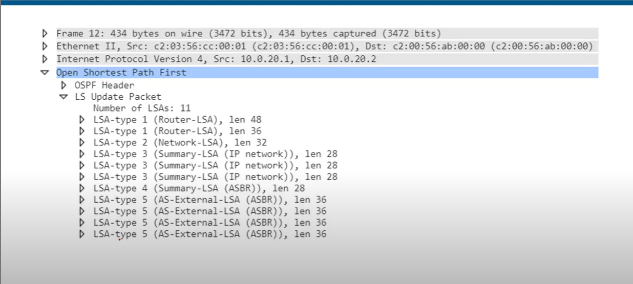
💡 - Hello messages are used for establishing and maintaining OSPF neighbour relationships.
- LSAs are used to share detailed routing and topology information within the OSPF domain.
- Hello messages are used for establishing and maintaining OSPF neighbour relationships.
- LSAs are used to share detailed routing and topology information within the OSPF domain.
Cost
- Open Shortest Path First(OSPF) uses cost as the value of metric value and uses a reference bandwidth of 100 Mbps for cost calculation. The formula to calculate the cost is Reference Bandwidth divided by interface bandwidth. For example, in the case of 10 Mbps Ethernet, OSPF metric cost value is 100 Mbps / 10 Mbps.

Modify the reference bandwidth
R1(config-router) **auto-cost reference-bandwidth** <u>megabits-per-second</u>
Manually configure the cost of an interface:
R1(config-if)**ip ospf cost** <u>cost</u>
Modify the interface bandwidth:
R1(config-if)**bandwith** kilobits-per-second
Which of these commands can be used to make a FastEthernet interface have an OSPF cost of 100?
- R(config-router)# auto-cost reference bandwidth 1000
Reference bandwidth/Interface bandwidth = cost
10000/100=100
💡 The SPF algorithm uses the cost of the outgoing interfaces toward the destination subnet, including the cost of the interface that connects to the subnet. The logic is illustrated in the following diagram.

Example Scenario
Scenario: You have two paths from Router A to Router D:
- Path 1: A → B → D (10 Mbps and 100 Mbps links, respectively).
- Path 2: A → C → D (100 Mbps links only).
Default Cost Calculation:
- Path 1: Cost = 10 (A → B) + 1 (B → D) = 11.
- Path 2: Cost = 1 (A → C) + 1 (C → D) = 2.
Result:
- OSPF chooses Path 2 because it has a lower total cost.

| Path | Total Cost [lower is better] |
| R1-R2-R3-R4-R5-R8 | 5 |
| R1-R5-R6-R8 | 4 |
| R1-R7-R8 | 3 (best) |
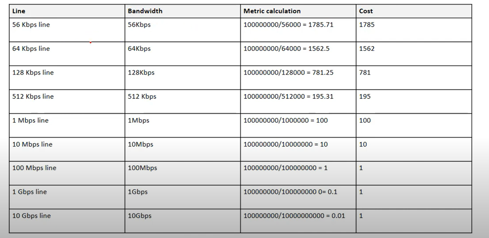
Wild Card Mask
- Wildcard masks are used to specify a range of network addresses. They are usually used with routing protocols (Such as OSPF) and access lists.
- A Wildcard mask is 32-bit long. It is an inverted subnet mask, with the zero bits indicating that the corresponding bit position must match the same bit position in the IP address.
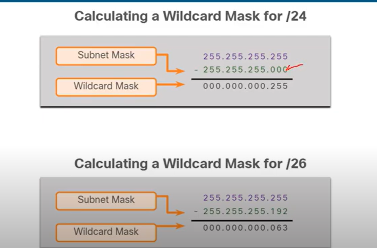
Note: Change all 0s to 255 and all 255s to 0. In the second one, the last number is 255 − 192 = 063.
OSPF States
- Down State: No Hello received.
- Init State: Hello packet received, but no 2-way communication yet. At this stage, Communication is One-way.
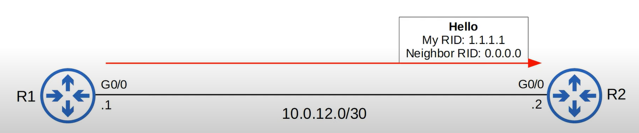
- 2-Way State: Bi-directional communication established (seen in DR/BDR election on broadcast/NBMA).
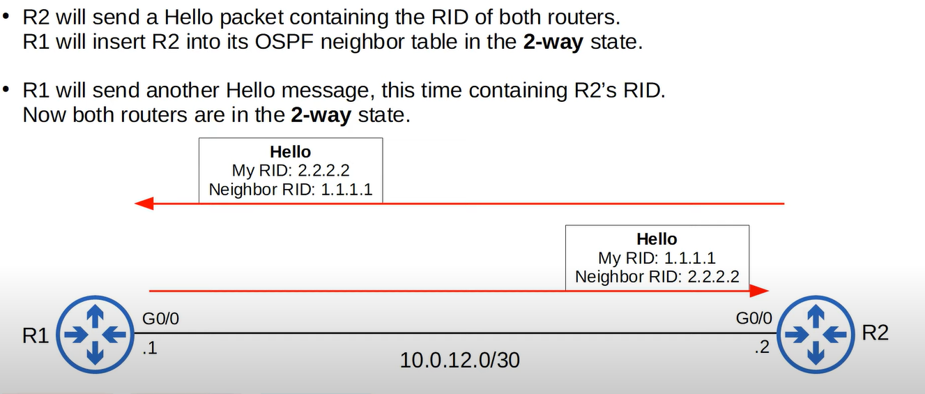
- ExStart State: Routers decide who will be master/slave for the database description (DBD) exchange.
- Exchange State: Routers exchange DBD packets (summaries of LSAs).
- Loading State: Routers send LSRs (Link State Requests) for missing LSAs.
- Full State: LSDBs fully synchronized between neighbors..
| ID | Name | Purpose |
| 1 | Hello | Neighbor Discovery and Maintenance |
| 2 | Database Description | Summary of the LSDB of the router. |
| 3 | Link-State Request (LSR) | Request specific LSAs from the neighbor. |
| 4 | Link-State Update (LSU) | Sends specific LSAs to the neighbor. |
| 5 | Link -State Acknowledgement(LSAck) | Used to acknowledge that the router received a massage. |
Router(config)# router ospf <process-id>      ! Start OSPF process (1–65535, local to router)
Router(config-router)# router-id <x.x.x.x>    ! (Optional) Set OSPF Router-ID
Router(config-router)# network <ip> <wildcard> area <area-id>   ! Advertise networks


Router(config)# router ospf 1
Router(config-router)# router-id 1.1.1.1
Router(config-router)# network 192.168.1.0 0.0.0.255 area 0
Router(config-router)# network 10.0.0.0 0.0.0.3 area 0
IR1(config)# router ospf 1
R1(config-router)# network 192.168.1.1 0.0.0.0 area 0

**VS**

R1(config)# router ospf 1
R1(config-router)# network 192.168.1.0 0.0.0.255 area 0
- Use
192.168.1.0 0.0.0.255When enabling OSPF on all interfaces within the192.168.1.0/24subnet. - Use
192.168.1.1 0.0.0.0When enabling OSPF on a specific interface with the IP address192.168.1.1.
Tip: To reduce manual configuration effort, use subnet-based configuration (192.168.1.0 0.0.0.255) for a larger network or dynamic environment. For specific control or precision, use interface-based configuration (192.168.1.1 0.0.0.0).
Verification Commands
show ip ospf neighbor      ! See adjacency & states
show ip ospf interface     ! Check OSPF timers, priority, area
show ip route ospf         ! Verify OSPF routes
show ip protocols          ! Protocol info & networks advertised
Configuring a Default Route in OSPF
Router(config)# router ospf 1
Router(config-router)# default-information originate always
The default-information originate always command in OSPF forces the advertisement of a default route (0.0.0.0/0) even if the router does not have a default static route in its routing table.
- Without
always**:** Only advertises if the router already knows a default route. - With
always**:** Forces advertisement, even if no default exists.

OSPF on Point-to-Point Links
- Point-to-point links are direct links between two routers.
- In OSPF, point-to-point networks do not need DR/BDR elections.
- Each router advertises its connected networks via LSAs (Link-State Advertisements).
Router(config)# interface g0/0 [interface connected to the neighbor router]
Router(config-if)# ip address 10.0.0.1 255.255.255.252
Router(config-if)# ip ospf 1 area 0
Router(config-if)# ip ospf network point-to-point
CCNA OSPF Questions
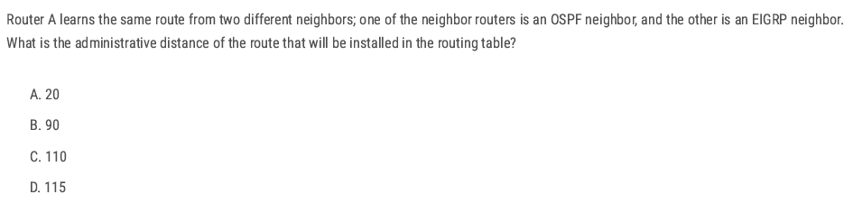
B (When multiple routing protocols advertise the same destination, the router installs the route with the lowest administrative distance (AD).)
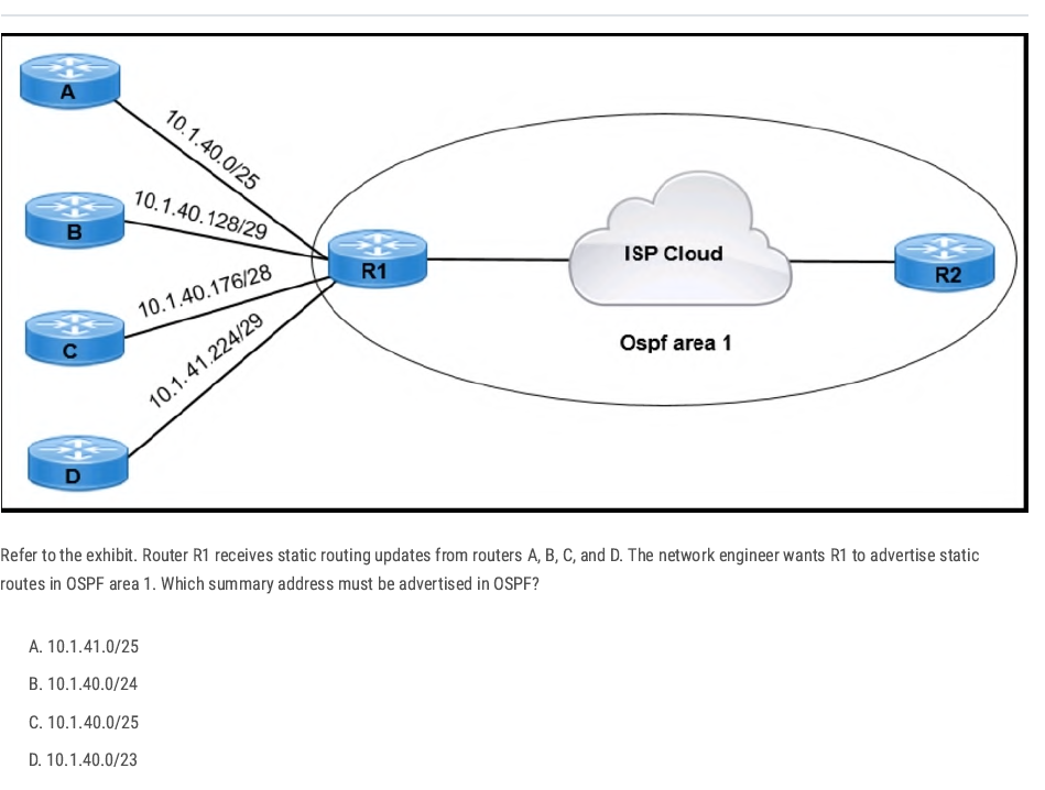
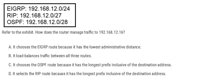
Check which routes contain 192.168.12.16
- EIGRP: 192.168.12.0/24 → range is 192.168.12.0–192.168.12.255 → ✅ contains 192.168.12.16
- RIP: 192.168.12.0/27 → range is 192.168.12.0–192.168.12.31 → ✅ contains 192.168.12.16
- OSPF: 192.168.12.0/28 → range is 192.168.12.0–192.168.12.15 → ❌ does not contain 192.168.12.16
Apply longest prefix match: 27 (RIP) is more specific than /24 (EIGRP). (Longest prefix match always wins, regardless of administrative distance.)
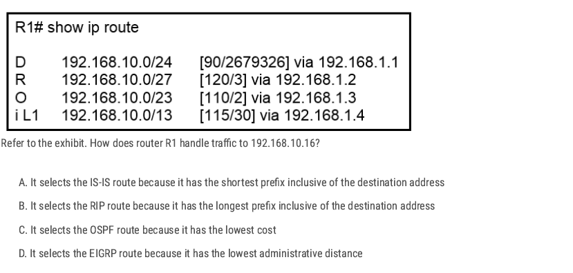
- EIGRP (D): 192.168.10.0/24 → 192.168.10.0 – 192.168.10.255
- RIP (R): 192.168.10.0/27 → 192.168.10.0 – 192.168.10.31
- OSPF (O): 192.168.10.0/23 → 192.168.10.0 – 192.168.11.255
- IS-IS (i L1): 192.168.10.0/13 → 192.168.8.0 – 192.168.15.255
All of these routes include 192.168.10.16. ✅
Apply the longest prefix match rule
- /13 → 8192 addresses (least specific)
- /23 → 512 addresses
- /24 → 256 addresses
- /27 → 32 addresses (most specific) Since /27 is the longest prefix (most specific match), the router will choose the RIP route.
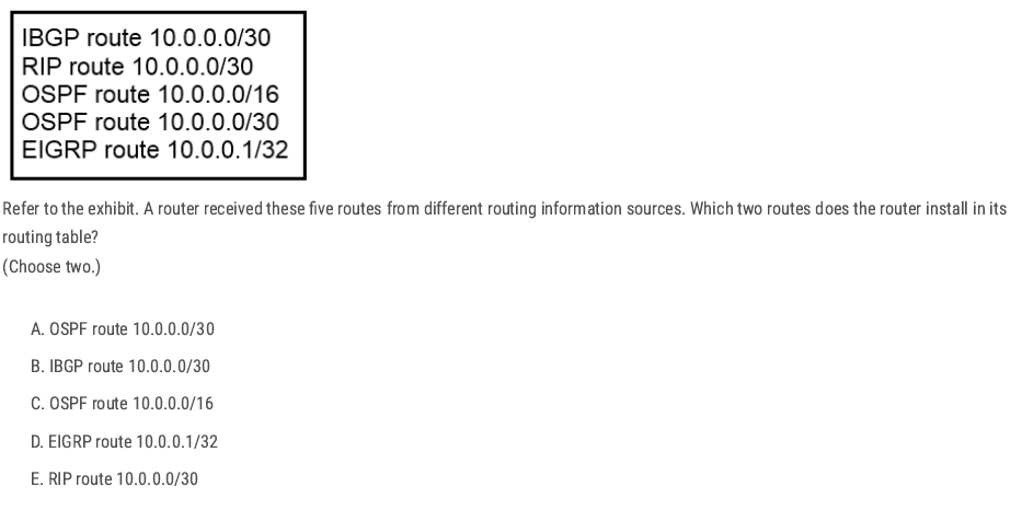
A and D ✅ (Because both of them have the lowest administrative distance)
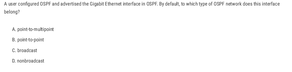
C. broadcast ✅ Ethernet (including FastEthernet and GigabitEthernet) interfaces, the default OSPF network type is broadcast.
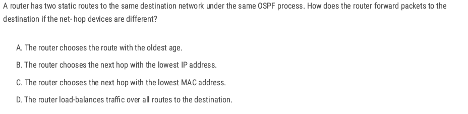
D ✅ If a router has two static routes to the same destination with the same administrative distance and metric, they are considered equal-cost routes.
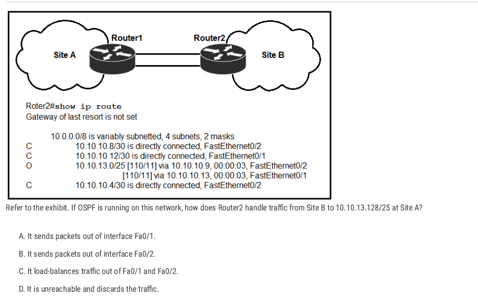
D ✅ The OSPF route present is 10.10.13.0/25 (via two next-hops). That covers addresses 10.10.13.0–10.10.13.127. The destination in question is 10.10.13.128/25 (addresses 10.10.13.128–10.10.13.255), which is a different /25, and no route for that network appears in the table.
A B✅
A C ✅
A ✅
A B E ✅
A C E ✅
D ✅
D E ✅
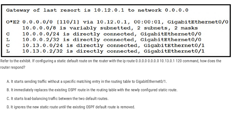
D ✅
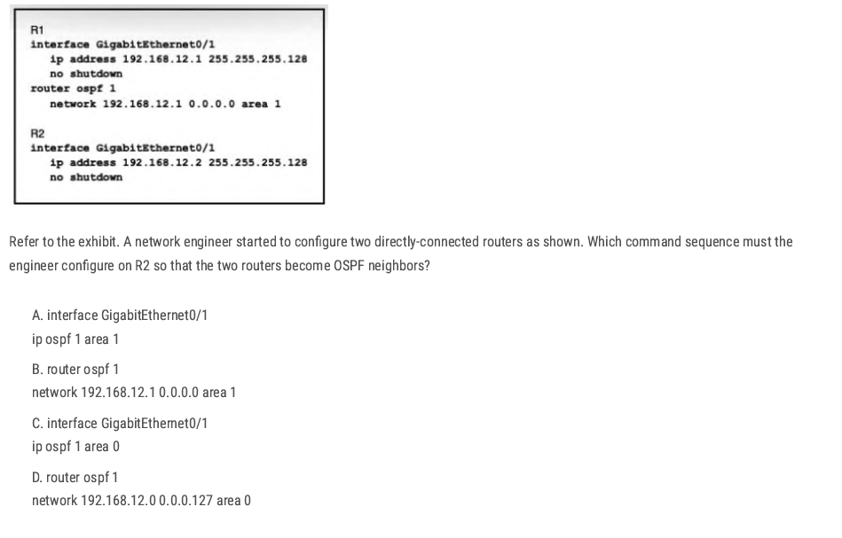
A✅
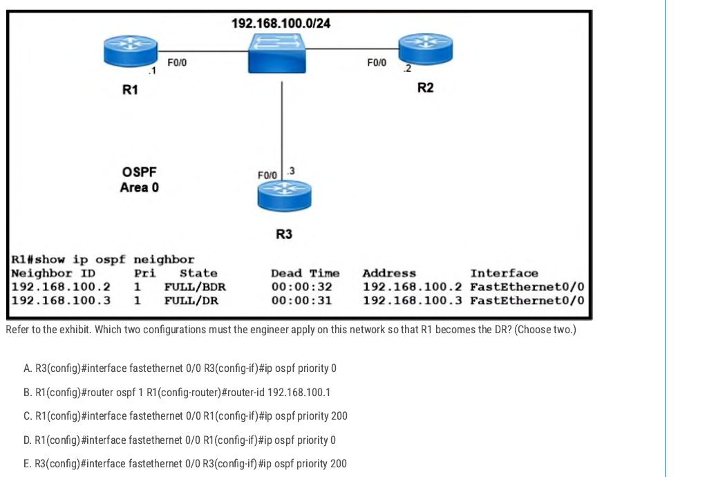
A C✅
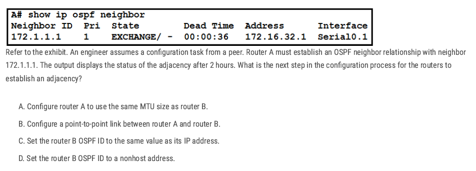
A ✅ The OSPF neighbors are stuck in the EXCHANGE state. This usually happens when the routers have different MTU sizes, so they cannot finish sharing database packets. Making both MTUs the same will let OSPF move to the FULL state.
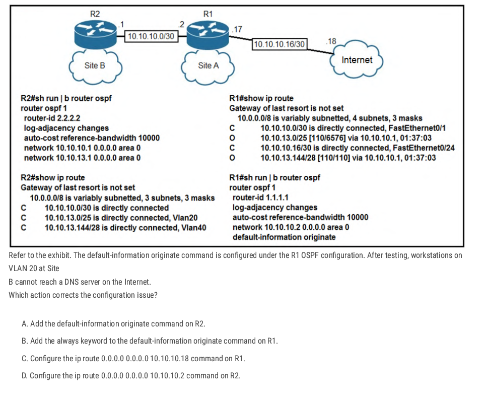
C. ✅
R1 has no default route, so it can’t advertise one with default-information originate. Adding a static default (ip route 0.0.0.0 0.0.0.0 10.10.10.18Let's R1 reach the Internet and share the route with R2 and Site B.
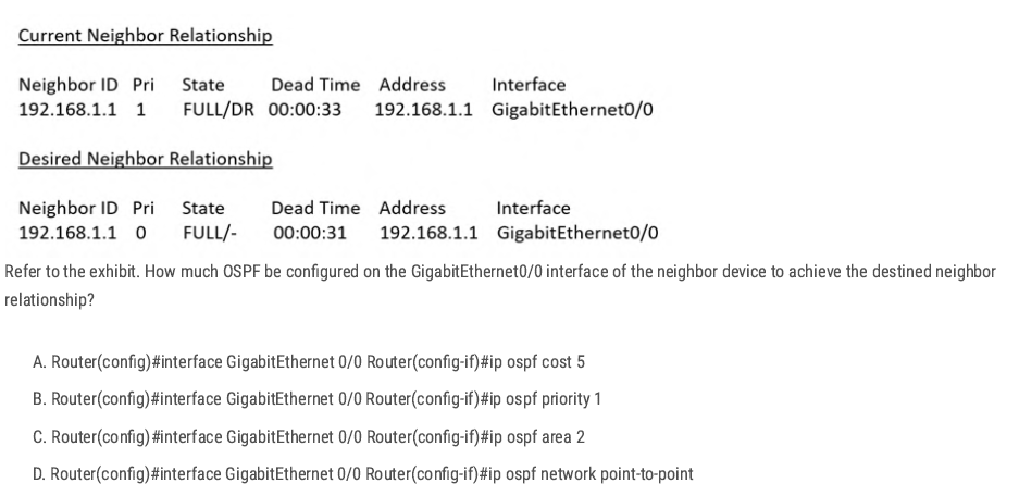
D. ✅
Changing the interface to ip ospf network point-to-point removes the DR/BDR election and makes the adjacency form as FULL/- instead of FULL/DR.
| Neighbor State | What it Means | When it Happens |
| FULL/DR | Neighbor is fully adjacent, and the neighbor is the Designated Router (DR). | On broadcast/multi-access networks (like Ethernet) when the neighbor wins DR election. |
| FULL/BDR | Neighbor is fully adjacent, and the neighbor is the Backup Designated Router (BDR). | On broadcast/multi-access networks when the neighbor is elected as BDR. |
| FULL/- | Neighbor is fully adjacent, but there is no DR/BDR election. | On point-to-point links, point-to-multipoint links, or loopbacks. |
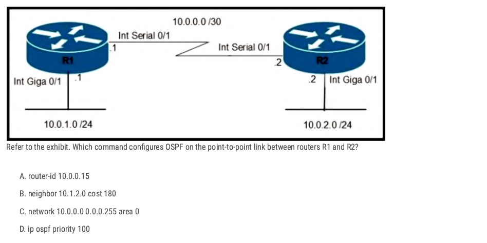
C. ✅
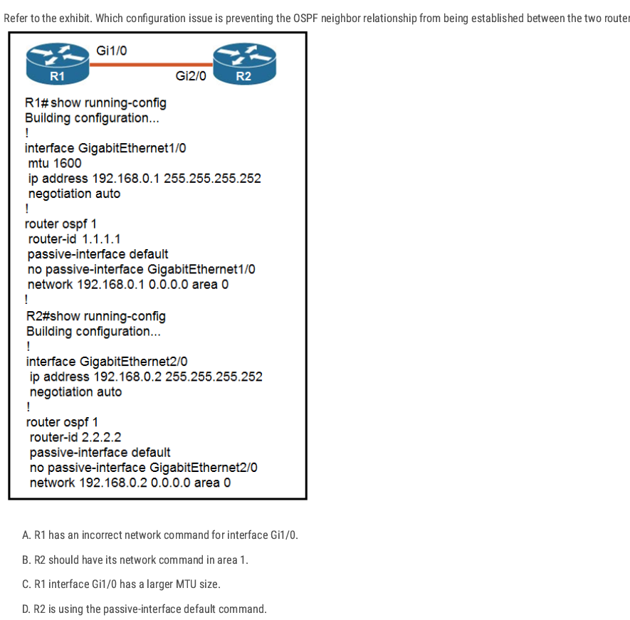
C. ✅ [During adjacency formation, OSPF checks that both neighbors have the same MTU.]
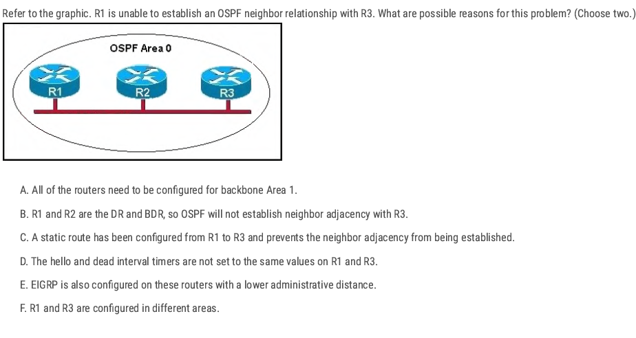
D F ✅
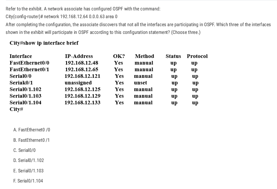
Network 192.168.12.64 0.0.0.63 equals to network 192.168.12.64/26.
192.168.12.64(Net ID) [192.168.12.65-192.168.12.126] 192.168.12.127(Broadcast Address) (Increment: 64)
B C D✅
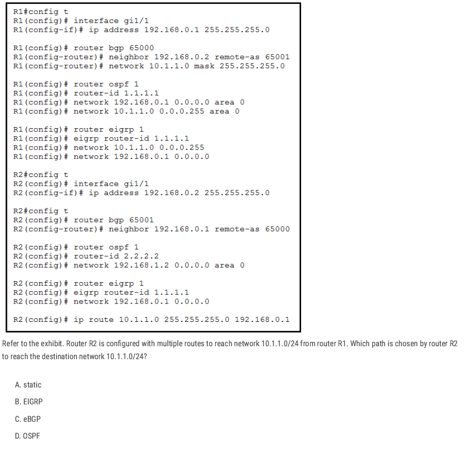
R2 has several possible sources for 10.1.1.0/24 (static, eBGP, OSPF, and EIGRP is misconfigured).
Cisco routers pick the route with the lowest administrative distance static route (0)
A✅
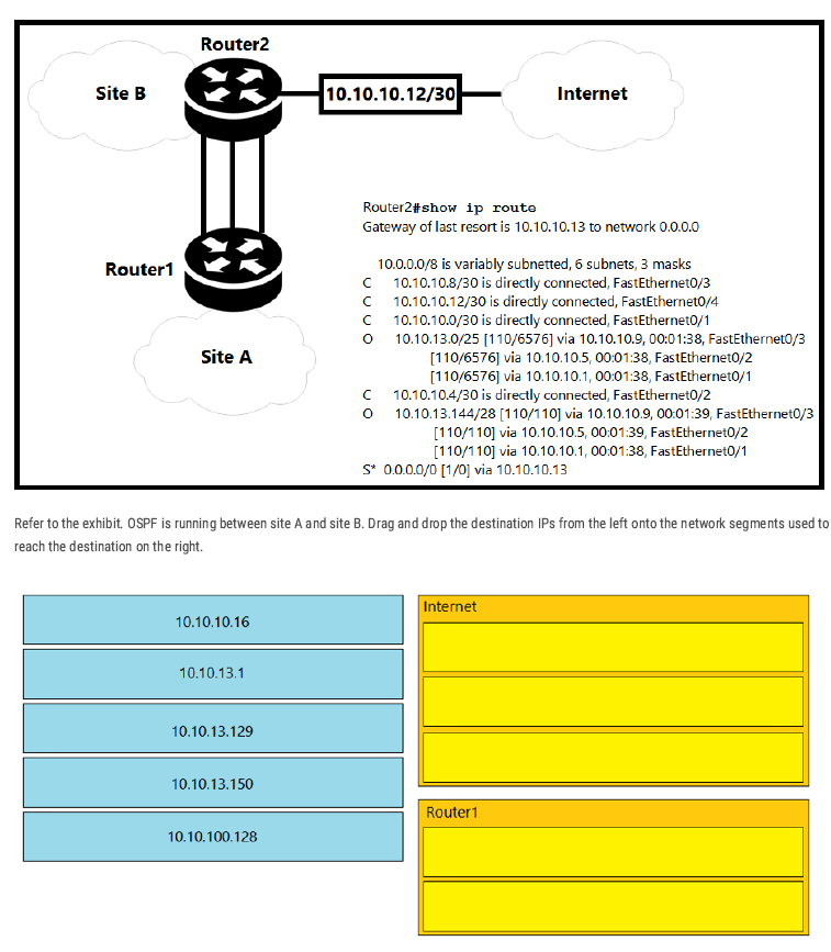
Internet: 10.10.10.16, 10.10.13.129, 10.10.100.128
Router1: 10.10.13.1, 10.10.13.150
Why: Router2 has OSPF routes only for 10.10.13.0/25 and 10.10.13.144/28 (to Router1). Addresses outside those (10.10.10.16, 10.10.13.129, 10.10.100.128) match no specific route, so they go via the default route to the Internet (0.0.0.0/0 → 10.10.10.13).
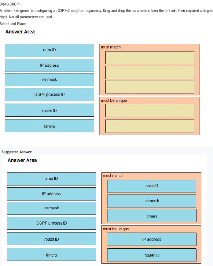
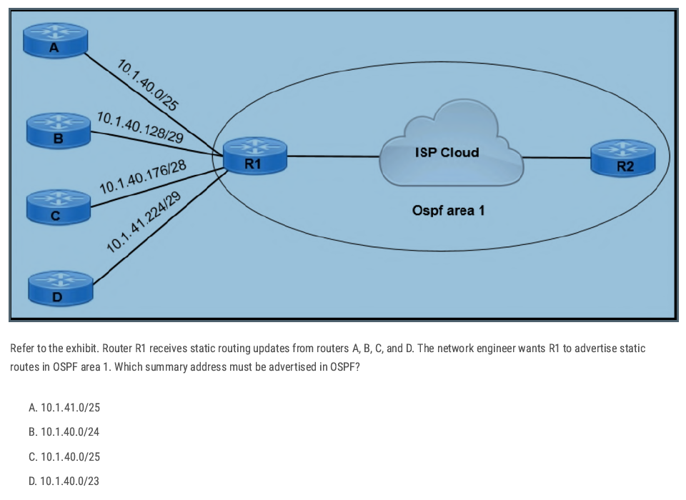
D✅
🔑 Easy Trick:
Look at the lowest subnet
→ Here it’s
10.1.40.0/25.Look at the highest subnet
→ Here it’s
10.1.41.224/29.Find the smallest network that covers from lowest to highest:
- Lowest = 10.1.40.x
Highest = 10.1.41.x
👉 Both fall under
10.1.40.0/23.
Check the options
- Only
/23includes both 10.1.40.x and 10.1.41.x.
- Only
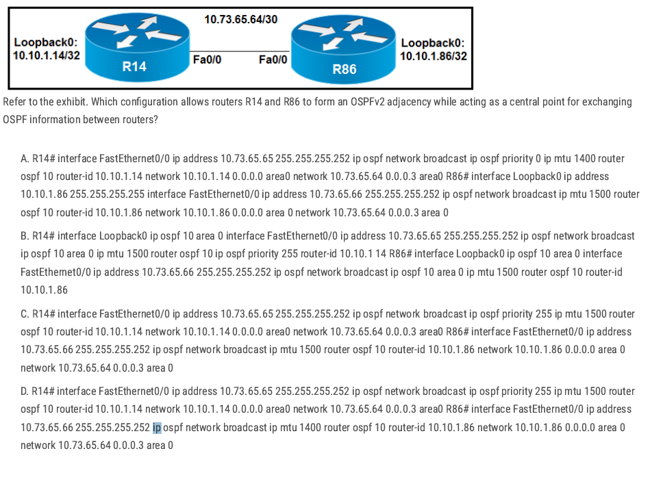
A and D have MTU mismatches (1400 vs 1500) — risky for adjacency/DBD.
Option B:
- The commands are presented in a scrambled/incorrect place (some
ip ospf priority/router-idappear under the wrong context), so it’s not a clean, valid interface-level OSPF config even though it tries to make R14 the DR.
C✅
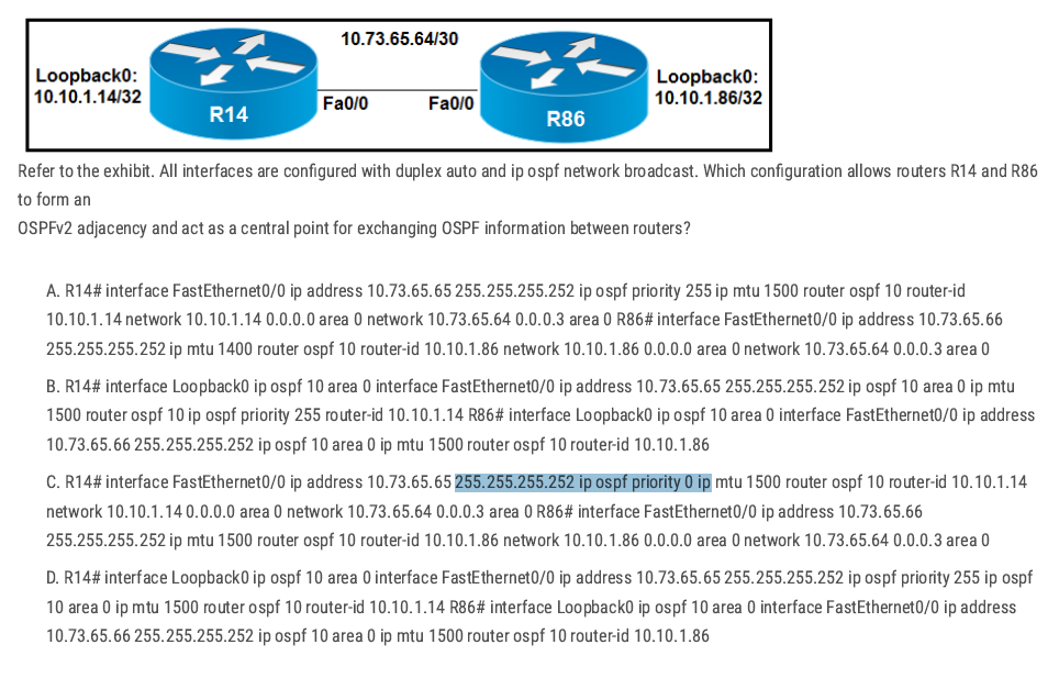
- A: MTU mismatch (R86 uses MTU 1400) — can break adjacency/DBD exchange.
- B: The commands are presented in a scrambled/incorrect place (some
ip ospf priority/router-idappear under the wrong context), so it’s not a clean, valid interface-level OSPF config even though it tries to make R14 the DR. - C: R14 is set to priority 0 (cannot become DR), so it cannot be the central point.
D✅
Single Area OSPF Configuration
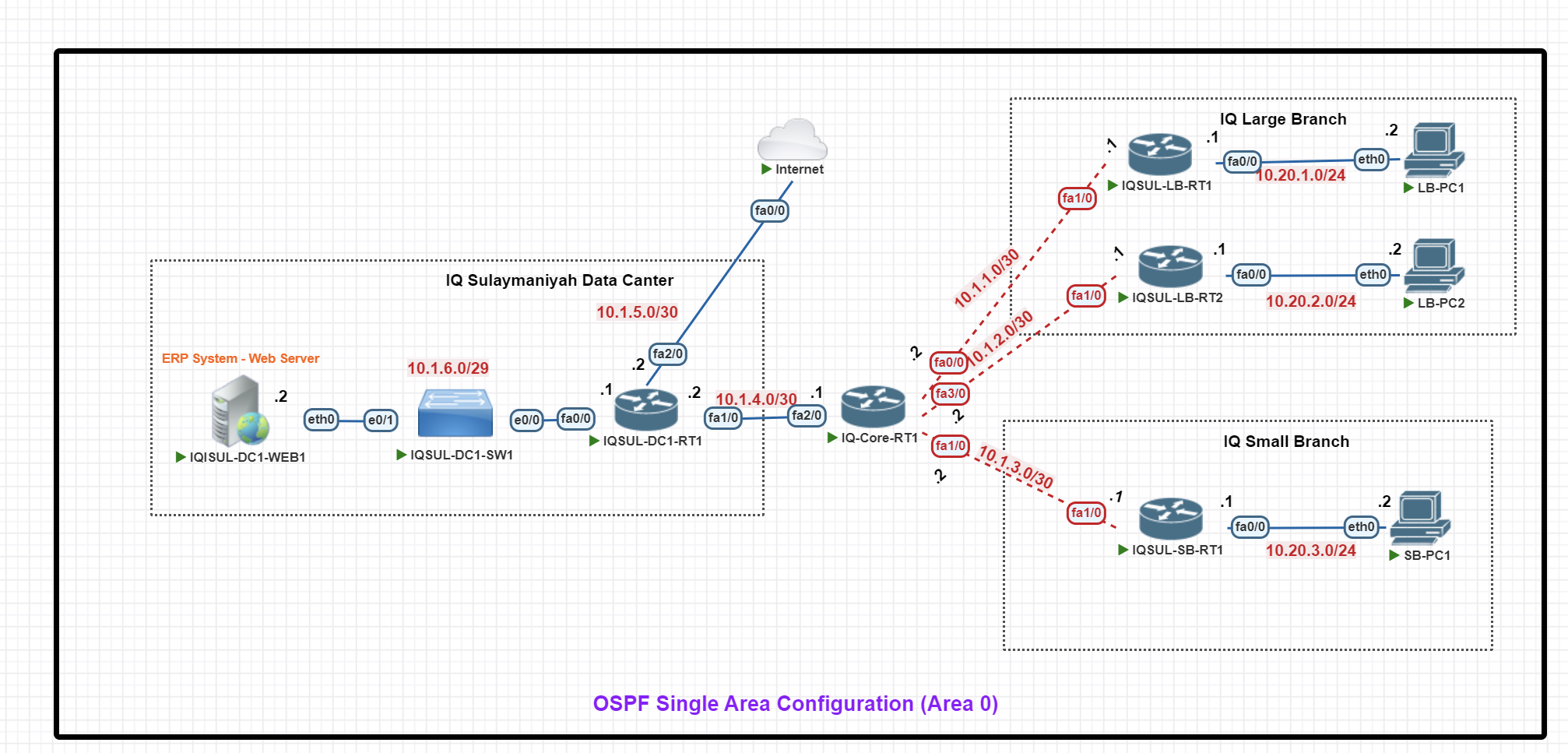
In this scenario, we will configure an OSPF Single Area (Area 0) Configuration for an enterprise setup with a central data center and two branch offices.
Key Components:
- IQ Sulaymaniyah Data Center: Hosts an ERP web server, a switch, and IQSUL-DC1-RT1, which connects to the Internet and branches via IQ-Core-RT1.
- IQ Core Router (IQ-Core-RT1): The main hub, linking the data center to branches using /30 P2P connections.
- IQ Large Branch: Has two routers (LB-RT1 & LB-RT2) for redundancy, with 10.20.1.0/24 and 10.20.2.0/24 subnets for end-user PCs.
- IQ Small Branch: Uses IQSUL-SB-RT1 and the 10.20.3.0/24 subnet for local PCs.
Basic IP Configuration
End-Point Devices IP configuration (VPC)
LB-PC1> ip 10.20.1.2 255.255.255.0 10.20.1.1
LB-PC1> save


LB-PC2> ip 10.20.2.2 255.255.255.0 10.20.2.1
LB-PC2> save


SB-PC1> ip 10.20.3.2 255.255.255.0 10.20.3.1
SB-PC1> save
IQ Large Branch Routers IP Configuration
IQSUL-LB-RT1#
IQSUL-LB-RT1#conf t
IQSUL-LB-RT1(config)#int fa0/0
IQSUL-LB-RT1(config-if)#ip add 10.20.1.1 255.255.255.0
IQSUL-LB-RT1(config-if)#no shut
IQSUL-LB-RT1(config-if)#exit
IQSUL-LB-RT1(config)#int fa 1/0
IQSUL-LB-RT1(config-if)#ip add 10.1.1.1 255.255.255.252
IQSUL-LB-RT1(config-if)#no shut
IQSUL-LB-RT1(config-if)#exit
IQSUL-LB-RT1(config)#exit
IQSUL-LB-RT1#wr
IQSUL-LB-RT2#
IQSUL-LB-RT2#conf t
IQSUL-LB-RT2(config)#int fa0/0
IQSUL-LB-RT2(config-if)#ip add 10.20.2.1 255.255.255.0
IQSUL-LB-RT2(config-if)#no shut
IQSUL-LB-RT2(config-if)#exit


IQSUL-LB-RT2(config)#int fa1/0
IQSUL-LB-RT2(config-if)#ip add 10.1.2.1 255.255.255.252
IQSUL-LB-RT2(config-if)#no shut
IQSUL-LB-RT2(config-if)#exit
IQSUL-LB-RT2(config)#exit
IQSUL-LB-RT2#wr
IQ Large Branch Routers IP Configuration
IQSUL-SB-RT1#conf t
IQSUL-SB-RT1(config)#int fa0/0
IQSUL-SB-RT1(config-if)#ip add 10.20.3.1 255.255.255.0
IQSUL-SB-RT1(config-if)#no shut
IQSUL-SB-RT1(config-if)#exit
IQSUL-SB-RT1(config)#int fa1/0
IQSUL-SB-RT1(config-if)#ip add 10.1.3.1 255.255.255.252
IQSUL-SB-RT1(config-if)#no shut
IQSUL-SB-RT1(config-if)#exit
IQSUL-SB-RT1(config)#exit
IQSUL-SB-RT1#wr
IQ Core Router IP Configuration
IQ-Core-RT1#conf t
IQ-Core-RT1(config)#int fa 0/0
IQ-Core-RT1(config-if)#ip add 10.1.1.2 255.255.255.252
IQ-Core-RT1(config-if)#no shut
IQ-Core-RT1(config-if)#exit

IQ-Core-RT1(config)#int fa 3/0
IQ-Core-RT1(config-if)#ip add 10.1.2.2 255.255.255.252
IQ-Core-RT1(config-if)#no shut
IQ-Core-RT1(config-if)#exit

IQ-Core-RT1(config)#int fa1/0
IQ-Core-RT1(config-if)#ip add 10.1.3.2 255.255.255.252
IQ-Core-RT1(config-if)#no shut
IQ-Core-RT1(config-if)#exit

IQ-Core-RT1(config)#int fa2/0
IQ-Core-RT1(config-if)#ip add 10.1.4.1 255.255.255.252
IQ-Core-RT1(config-if)#no shut

IQ-Core-RT1(config)#exit
IQ-Core-RT1#wr
IQ Data Center Router IP Configuration
IQSUL-DC1-RT1#conf t
IQSUL-DC1-RT1(config)#int fa 1/0
IQSUL-DC1-RT1(config-if)#ip add 10.1.4.2 255.255.255.252
IQSUL-DC1-RT1(config-if)#no shut
IQSUL-DC1-RT1(config)#int fa 2/0
IQSUL-DC1-RT1(config-if)#ip add 10.1.5.2 255.255.255.252
IQSUL-DC1-RT1(config-if)#no shut
IQSUL-DC1-RT1(config-if)#exit
IQSUL-DC1-RT1(config)#int fa0/0
IQSUL-DC1-RT1(config-if)#ip add 10.1.6.1 255.255.255.248
IQSUL-DC1-RT1(config-if)#no shut
IQSUL-DC1-RT1(config-if)#exit
IQSUL-DC1-RT1(config)#exit
IQSUL-DC1-RT1#wr
Internet#conf t
Internet(config)#int fa0/0
Internet(config-if)#ip add 10.1.5.1 255.255.255.252
Internet(config-if)#no shut
Internet(config-if)#exit
Internet(config)#exi
IQ Web Server IP Configuration
IQSUL-DC1-WEB1#conf t
IQSUL-DC1-WEB1(config)#int fa0/0
IQSUL-DC1-WEB1(config-if)#ip add 10.1.6.2 255.255.255.248
IQSUL-DC1-WEB1(config-if)#no shut
IQSUL-DC1-WEB1(config-if)#exit
IQSUL-DC1-WEB1(config)#exit
IQSUL-DC1-WEB1#wr
OSPF Configuration
IQ Large Branch OSPF Configuration
IQSUL-LB-RT1#conf t
IQSUL-LB-RT1(config)#
IQSUL-LB-RT1(config)#router ospf 1
IQSUL-LB-RT1(config-router)#router-id 1.1.1.1
IQSUL-LB-RT1(config-router)#network 10.20.1.0 0.0.0.255 area 0
IQSUL-LB-RT1(config-router)#network 10.1.1.1 0.0.0.0 area 0
IQSUL-LB-RT1(config-router)#passive-interface fa0/0
IQSUL-LB-RT1(config-router)#exit
IQSUL-LB-RT1(config)#exit
IQSUL-LB-RT1#wr
IQSUL-LB-RT2#conf t
IQSUL-LB-RT2(config)#
IQSUL-LB-RT2(config)#router ospf 1
IQSUL-LB-RT2(config-router)#router-id 2.2.2.2
IQSUL-LB-RT2(config-router)#network 10.20.2.0 0.0.0.255 area 0
IQSUL-LB-RT2(config-router)#network 10.1.2.1 0.0.0.0 area 0
IQSUL-LB-RT2(config-router)#passive-interface fa0/0
IQSUL-LB-RT2(config-router)#exit
IQSUL-LB-RT2(config)#exit
IQSUL-LB-RT2#exit
IQSUL-LB-RT2#wr
IQ Small Branch Routers OSPF Configuration
IQSUL-SB-RT1#conf t
IQSUL-SB-RT1(config)#
IQSUL-SB-RT1(config)#router ospf 1
IQSUL-SB-RT1(config-router)#router-id 3.3.3.3
IQSUL-SB-RT1(config-router)#network 10.20.3.0 0.0.0.255 area 0
IQSUL-SB-RT1(config-router)#network 10.1.3.1 0.0.0.0  area 0
IQSUL-SB-RT1(config-router)#passive-interface fa0/0
IQSUL-SB-RT1(config-router)#exit
IQSUL-SB-RT1(config)#exit
IQSUL-SB-RT1#
IQSUL-SB-RT1#wr
IQ Core Router OSPF Configuration
IQ-Core-RT1#
IQ-Core-RT1#conf t
IQ-Core-RT1(config)#int fa0/0
IQ-Core-RT1(config-if)#ip ospf priority 200
IQ-Core-RT1(config)#int fa3/0
IQ-Core-RT1(config-if)#ip ospf priority 200
IQ-Core-RT1(config-if)#exit
IQ-Core-RT1(config)#in fa1/0
IQ-Core-RT1(config-if)#ip ospf priority 200
IQ-Core-RT1(config-if)#exit
IQ-Core-RT1(config)#in fa2/0
IQ-Core-RT1(config-if)#ip ospf priority 200
IQ-Core-RT1(config-if)#exit
IQ-Core-RT1(config)#exit
IQ-Core-RT1#wr
IQ-Core-RT1#conf t
IQ-Core-RT1(config)#
IQ-Core-RT1(config)#router ospf 1
IQ-Core-RT1(config-router)#router-id 10.10.10.10
IQ-Core-RT1(config-router)#network 10.1.1.2 0.0.0.0 area 0
IQ-Core-RT1(config-router)#network 10.1.2.2 0.0.0.0 area 0
IQ-Core-RT1(config-router)#network 10.1.3.2 0.0.0.0 area 0
IQ-Core-RT1(config-router)#network 10.1.4.1 0.0.0.0 area 0
IQ-Core-RT1(config-router)#exit
IQ-Core-RT1(config)#EXIT
IQ-Core-RT1#clear ip ospf proces
IQ Data Center Router OSPF Configuration
IQSUL-DC1-RT1#
IQSUL-DC1-RT1#conf t
IQSUL-DC1-RT1(config)#router ospf 1
IQSUL-DC1-RT1(config-router)#router-id 6.6.6.6
IQSUL-DC1-RT1(config-router)#network 10.1.4.2 0.0.0.0 area 0
IQSUL-DC1-RT1(config-router)#network 10.1.5.2 0.0.0.0 area 0
IQSUL-DC1-RT1(config-router)#network 10.1.6.0 0.0.0.7 area 0
IQSUL-DC1-RT1(config-router)#passive-interface fa0/0
IQSUL-DC1-RT1(config-router)#exit
IQSUL-DC1-RT1(config)#exit
IQSUL-DC1-RT1#exit
debug ip icmp debug ip packet detail
Multi-Area OSPF Configuration
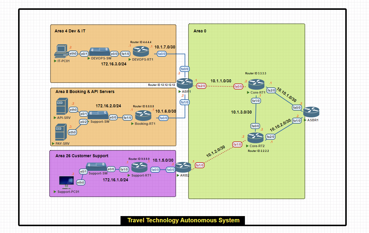
In this scenario, we will configure a multi-area OSPF network within a single autonomous system for a travel technology company.
- Area 0 (Backbone): Connects all areas and external networks.
- Area 4 (Dev & IT): Hosts development resources and IT infrastructure.
- Area 8 (Booking & API Servers): Houses critical booking and payment servers.
- Area 26 (Customer Support): Manages customer support operations.
Basic IP Configuration
Core Routers IP Configuration
Core-RT1#conf t
Core-RT1(config)#int fa0/0
Core-RT1(config-if)#ip add 10.1.1.2 255.255.255.252
Core-RT1(config-if)#no shut
Core-RT1(config-if)#exit

Core-RT1(config)#int fa1/0
Core-RT1(config-if)#ip add 10.1.3.1 255.255.255.252
Core-RT1(config-if)#no shut
Core-RT1(config-if)#exit

Core-RT1(config)#int fa2/0
Core-RT1(config-if)#ip add 10.10.1.1 255.255.255.252
Core-RT1(config-if)#no shut


Core-RT1(config-if)#exit
Core-RT1(config)#exit
Core-RT1#wr
Core-RT2#conf t
Core-RT2(config)#int fa0/0
Core-RT2(config-if)#ip add 10.1.3.2 255.255.255.252
Core-RT2(config-if)#no shu

Core-RT2(config-if)#exit
Core-RT2(config)#int fa1/0
Core-RT2(config-if)#ip add 10.1.2.2 255.255.255.252
Core-RT2(config-if)#no shut
Core-RT2(config-if)#exit

Core-RT2(config)#int fa2/0
Core-RT2(config-if)#ip add  10.10.2.1 255.255.255.0
Core-RT2(config-if)#no shut
Core-RT2(config-if)#exit
Core-RT2(config)#exit
Core-RT2#wr
Area Border Router (ABR) IP Configuration
ABR1#conf t
ABR1(config)#int fa0/0
ABR1(config-if)#ip add 10.1.7.2 255.255.255.252
ABR1(config-if)#no shut
ABR1(config-if)#exit

ABR1(config)#int fa1/0
ABR1(config-if)#ip add 10.1.6.2 255.255.255.252
ABR1(config-if)#no shut
ABR1(config-if)#exit
ABR1(config)#int fa2/0
ABR1(config-if)#ip add 10.1.1.1 255.255.255.252
ABR1(config-if)#no shut
ABR1(config-if)#exit
ABR1(config)#exit
ABR1#wr
ARB2(config)#int fa1/0
ARB2(config-if)#ip add 10.1.2.1 255.255.255.252
ARB2(config-if)#no shut
ARB2(config-if)#exit

ARB2(config)#int fa0/0
ARB2(config-if)#ip add 10.1.5.2 255.255.255.252
ARB2(config-if)#no shut
ARB2(config-if)#exit
ARB2(config)#exit
ARB2#wr
Autonomous System Border Router (ASBR) IP Configuration
ASBR1(config)#int fa1/0
ASBR1(config-if)#ip add 10.10.2.2 255.255.255.252
ASBR1(config-if)#no shut
ASBR1(config-if)#exit
ASBR1(config)#int fa0/0
ASBR1(config-if)#ip add 10.10.1.2 255.255.255.252
ASBR1(config-if)#no shut
ASBR1(config-if)#exit
ASBR1(config)#exit
ASBR1#wr
Support Router and End-Device IP Configuration
Support-RT1#conf t
Support-RT1(config)#int fa0/0
Support-RT1(config-if)#ip add 10.1.5.1 255.255.255.252
Support-RT1(config-if)#no shut
Support-RT1(config-if)#exit
Support-RT1(config)#int fa1/0
Support-RT1(config-if)#ip add 172.16.1.1 255.255.255.0
Support-RT1(config-if)#no shut
Support-RT1(config-if)#exit
Support-RT1(config)#exit
Support-RT1#q
Support-RT1#wr
Support-PC01> ip 172.16.1.2/24 172.16.1.1
Support-PC01> save
Booking Router and End-Device IP Configuration
Booking-RT1#conf t
Booking-RT1(config)#int fa0/0
Booking-RT1(config-if)#ip add 10.1.6.1 255.255.255.252
Booking-RT1(config-if)#no shut
Booking-RT1(config-if)#exit
Booking-RT1(config)#int f1/0
Booking-RT1(config-if)#ip add 172.16.2.1 255.255.255.0
Booking-RT1(config-if)#no shut
Booking-RT1(config-if)#exit
Booking-RT1(config)#exit
Booking-RT1#wr
API-SRV> ip 172.16.2.2/24 172.16.2.1
API-SRV> save
PAY-SRV> ip 172.16.2.3/24 172.16.1.1
PAY-SRV> save
DEV&IT Router and End-Device IP Configuration
DEVOPS-RT1#conf t
DEVOPS-RT1(config)#int fa0/0
DEVOPS-RT1(config-if)#ip add 10.1.7.1 255.255.255.252
DEVOPS-RT1(config-if)#no shut
DEVOPS-RT1(config-if)#exit

DEVOPS-RT1(config)#int fa1/0
DEVOPS-RT1(config-if)#ip add 172.16.3.1 255.255.255.0
DEVOPS-RT1(config-if)#no shut
DEVOPS-RT1(config-if)#exit
DEVOPS-RT1(config)#exit
DEVOPS-RT1#wr
IT-PC01> ip 172.16.3.2/24 172.16.3.1
IT-PC01> save
OSPF Configuration
Area Border Router (ABR) 1 OSPF Configuration
ABR1(config)#router ospf 10
ABR1(config-router)#router-id 12.12.12.12
ABR1(config-router)#network 10.1.7.2 0.0.0.0 area 4
ABR1(config-router)#network 10.1.6.2 0.0.0.0 area 8
ABR1(config-router)#network 10.1.1.1 0.0.0.0 area 0
ABR1(config-router)#exit
ABR1(config)#exit
ABR1#wr
DEV&IT Router OSPF Configuration
DEVOPS-RT1#conf t
DEVOPS-RT1(config)#router ospf 1
DEVOPS-RT1(config-router)#router-id 4.4.4.4
DEVOPS-RT1(config-router)#network 10.1.7.1 0.0.0.0 area 4
DEVOPS-RT1(config-router)#network 172.16.3.0 0.0.0.255 area 4
DEVOPS-RT1(config-router)#passive-interface fa1/0
DEVOPS-RT1(config-router)#exit
DEVOPS-RT1(config)#exit
DEVOPS-RT1#wr
Booking Router OSPF Configuration
Booking-RT1(config)#router ospf 8
Booking-RT1(config-router)#router-id 8.8.8.8
Booking-RT1(config-router)#network 10.1.6.1 0.0.0.0 area 8
Booking-RT1(config-router)#network 172.16.2.0 0.0.0.255 area 8
Booking-RT1(config-router)#passive-interface fa1/0
Booking-RT1(config-router)#exit
Booking-RT1(config)#exit
Booking-RT1#wr
Area Border Router (ABR) 2 OSPF Configuration
ARB2(config)#router ospf 11
ARB2(config-router)#router-id 12.12.12.12
ARB2(config-router)#network 10.1.2.1 0.0.0.0 area 0
ARB2(config-router)# network 10.1.5.2 0.0.0.0 area 26
ARB2(config-router)#exit
ARB2(config)#exit
ARB2#wr
Support Router OSPF Configuration
Support-RT1(config)#router ospf 26
Support-RT1(config-router)#router-id 9.9.9.9
Support-RT1(config-router)#network 10.1.5.1 0.0.0.0 area 26
Support-RT1(config-router)#network 172.16.1.0  0.0.0.255 area 26
Support-RT1(config-router)#passive-interface fa1/0
Support-RT1(config-router)#exit
Support-RT1(config)#exit
Support-RT1#
Core Routers OSPF Configuration
Core-RT1(config)#router ospf 5
Core-RT1(config-router)#router-id 3.3.3.3
Core-RT1(config-router)#network 10.1.1.2 0.0.0.0 area 0
Core-RT1(config-router)#network 10.1.3.1 0.0.0.0 area 0
Core-RT1(config-router)#network 10.10.1.1 0.0.0.0 area 0
Core-RT1(config-router)#exit
Core-RT1(config)#exit
Core-RT2#conf t
Core-RT2(config)#router ospf 6
Core-RT2(config-router)#router-id 2.2.2.2
Core-RT2(config-router)#network 10.1.3.2 0.0.0.0 area 0
Core-RT2(config-router)#network 10.1.2.2 0.0.0.0 area 0
Core-RT2(config-router)#network 10.1.2.2 0.0.0.0 area 0
Core-RT2(config-router)#exit
Core-RT2(config)#exit
Core-RT2#
Verify OSPF Configuration
R#show ip ospf neighbor
R# show ip ospf neighbor detail
R#show ip ospf interface brief
R# debug ip ospf adj
R# debug ip ospf ?
| adj | OSPF adjacency events |
| capability | OSPF Capability |
| database-timer | OSPF database timer |
| events | OSPF events |
| flood | OSPF flooding |
| hello | OSPF hello events |
| lsa-generation | OSPF lsa generation |
| monitor | OSPF spf monitoring |
| tree | OSPF database tree |
| packet | OSPF packets |
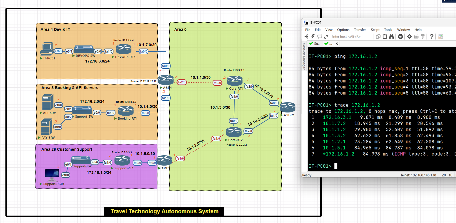
LAB
OSPF configuration Single Area
R1(confgi)# router ospf 1[process id]
R1(config-router)# network 192.168.0.0 0.0.0.255 [wildcard mask] area 0 [backbone area]
R1(config-router)# network 192.168.1.0 0.0.0.255 [wildcard mask] area 0


R2(confgi)# router ospf 1[process id]
R2(config-router)# network 192.168.1.0 0.0.0.255 [wildcard mask] area 0 [backbone area]
R2(config-router)# network 192.168.2.0 0.0.0.255 [wildcard mask] area 0
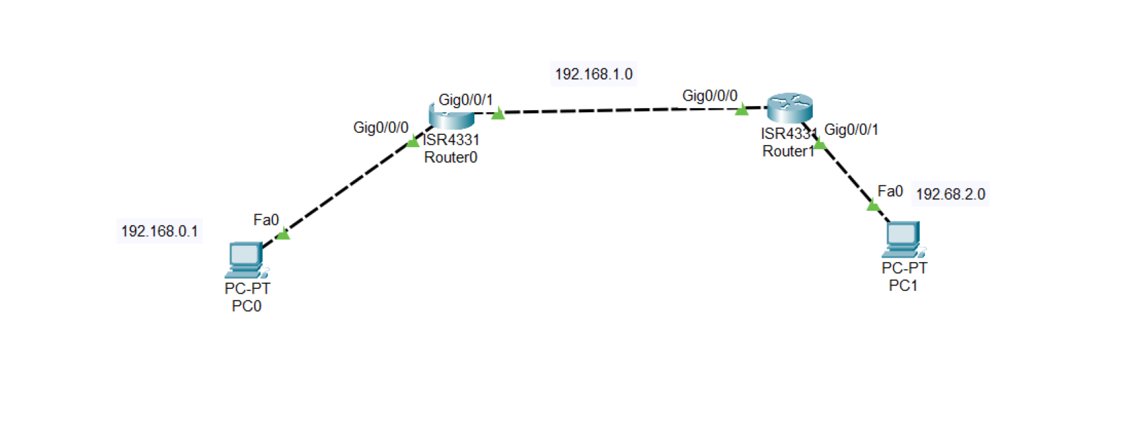
.
R1(confgi)# show ip ospf interface
.
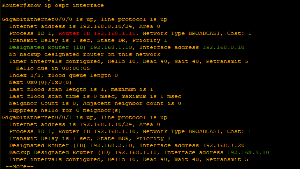
As you can see, The router connected into two interfaces[192.168.0.10-192.168.1.10] highest IP address elected as a router ID 192.168.1.10 is the router ID.
Also selected as a DR and the another router selected as a BDR
Router#show ip ospf neighbor
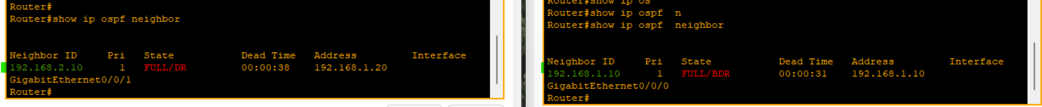
Implementing Single Area cost
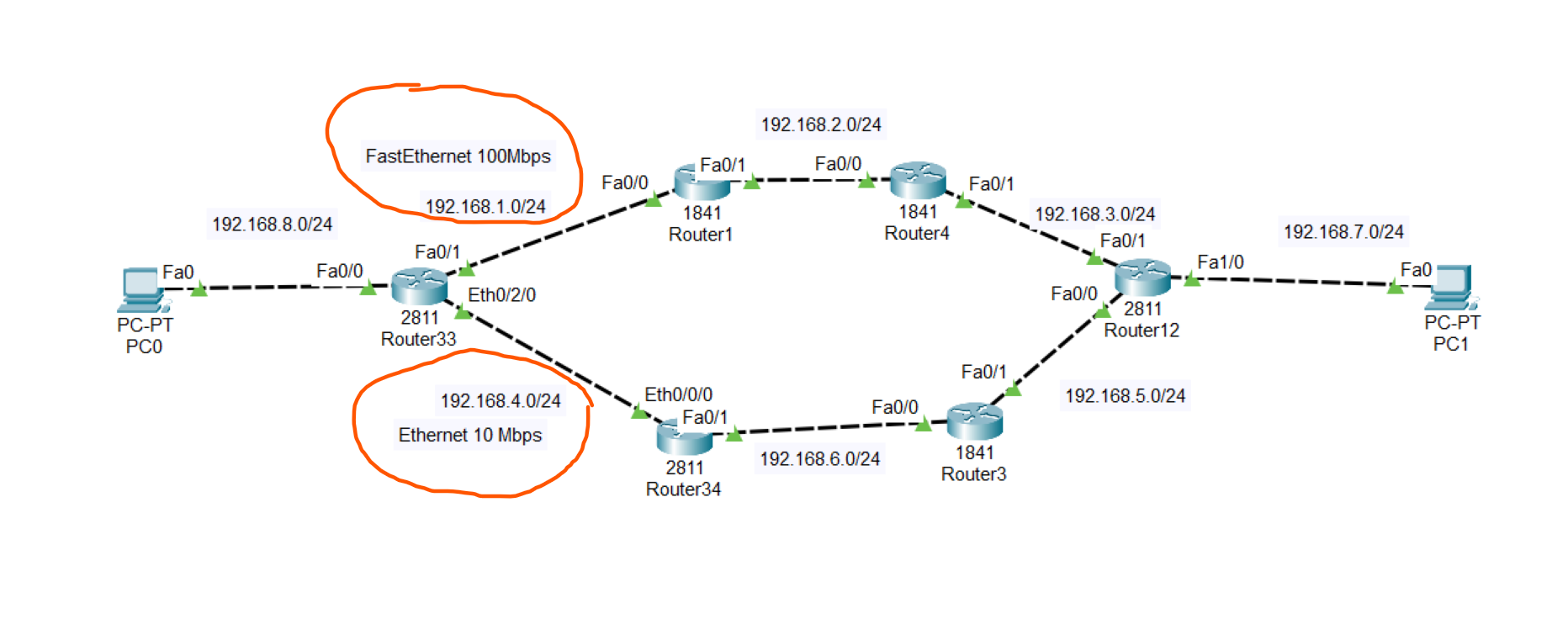
To know which path used by the OSPF to send data to other computer we use the command below on the on PC0
.
tracert [ip]
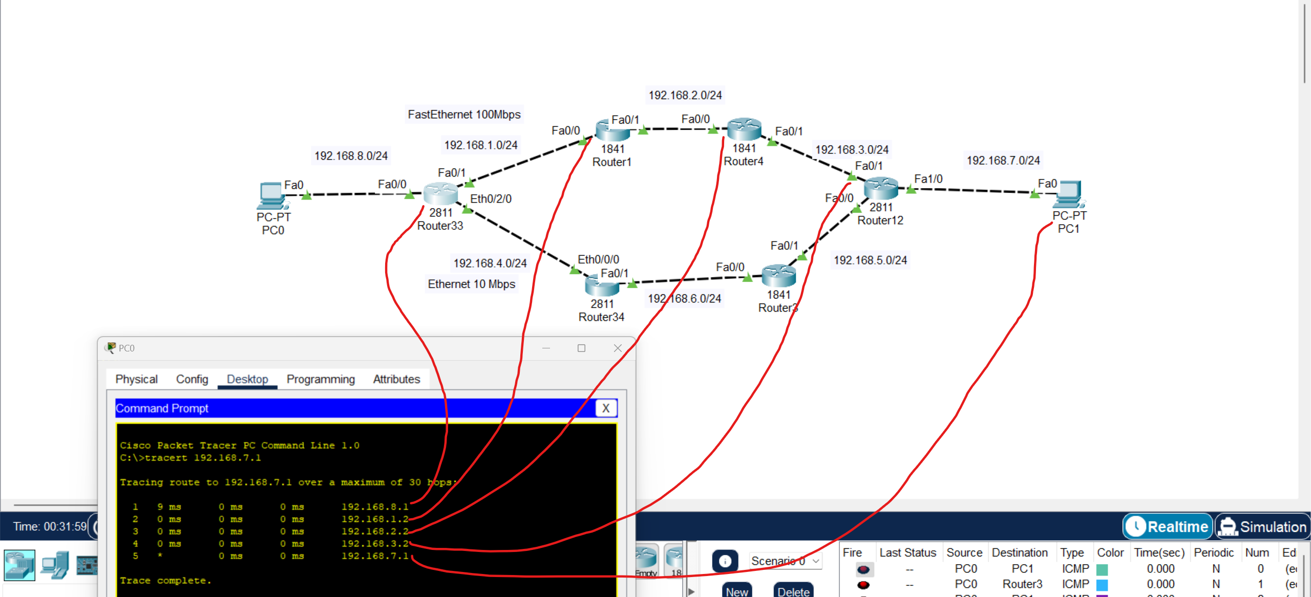
We using exit ports to count cost
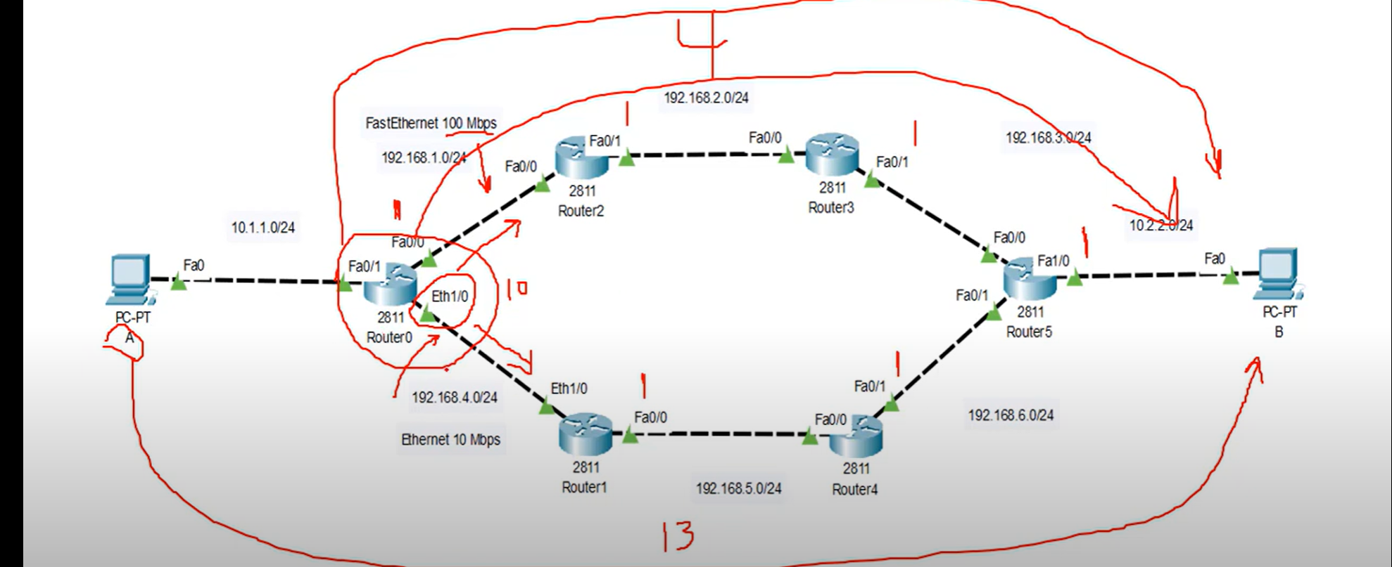
Note: as you can see the cost of Fast Ethernet =1 and the summation of all existing interfaces = 4 but cost of Ethernet = 10 + 3 Fast Ethernet = 13 not acceptable by OSPF.
DR and BDR Election
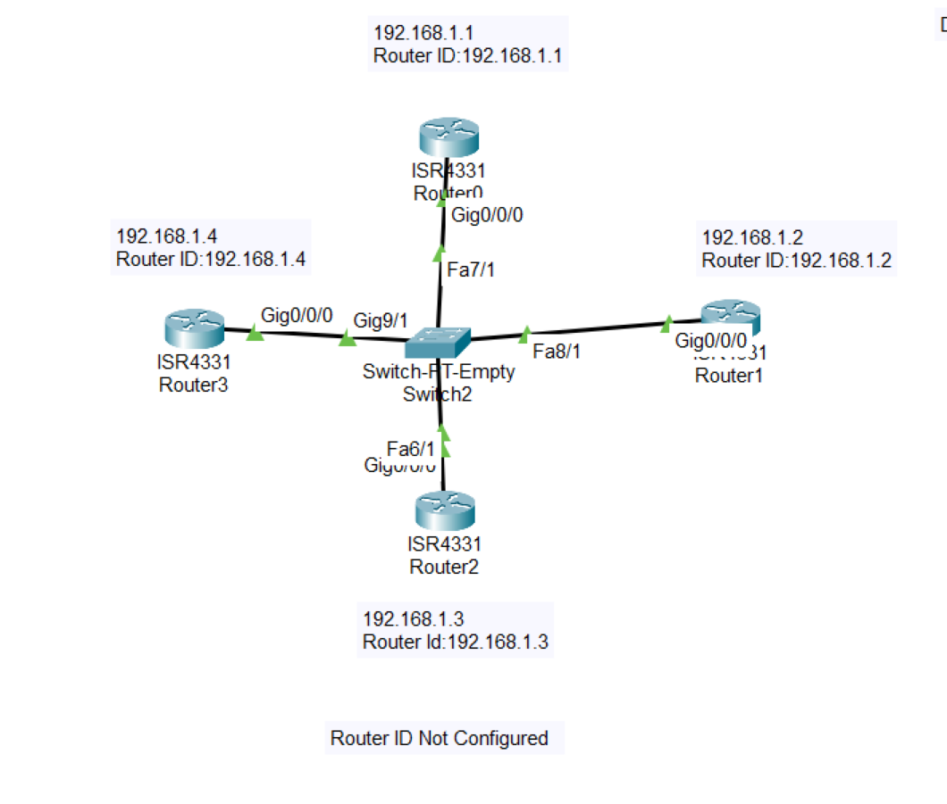
💡 In this example, Router ID is not configured and the IP Address of the router is defined as a Router ID
- Using this command below you could track every step of the process of the election
Router#debug ip ospf adj
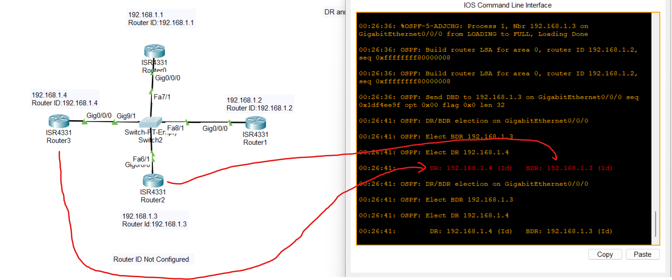
The highest IP address was elected as DR and the second Highest IP address was elected as BDR.
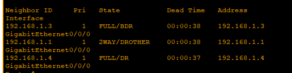
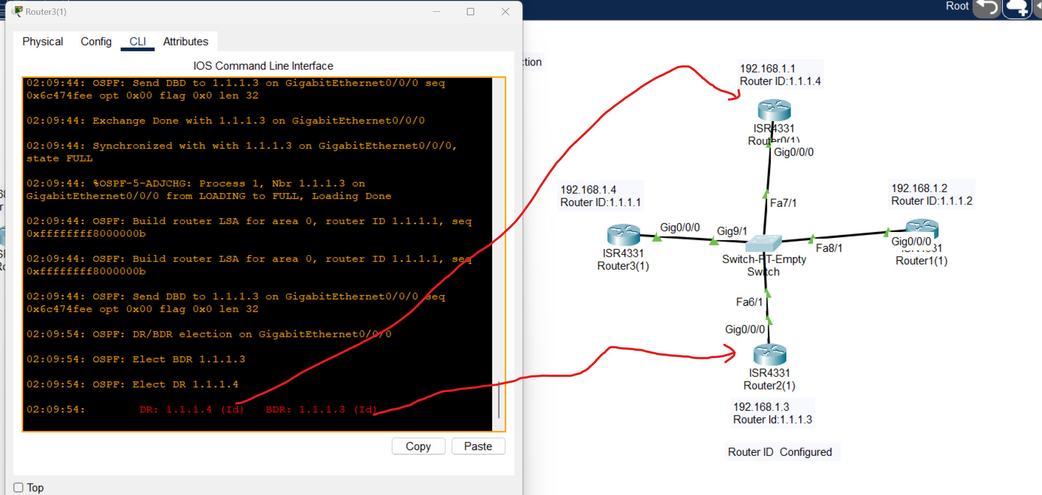
When Router is configured OSPF protocol elects the highest ID as a DR and the second Highest as a BDR.
Multi-Area OSPF Configuration
.
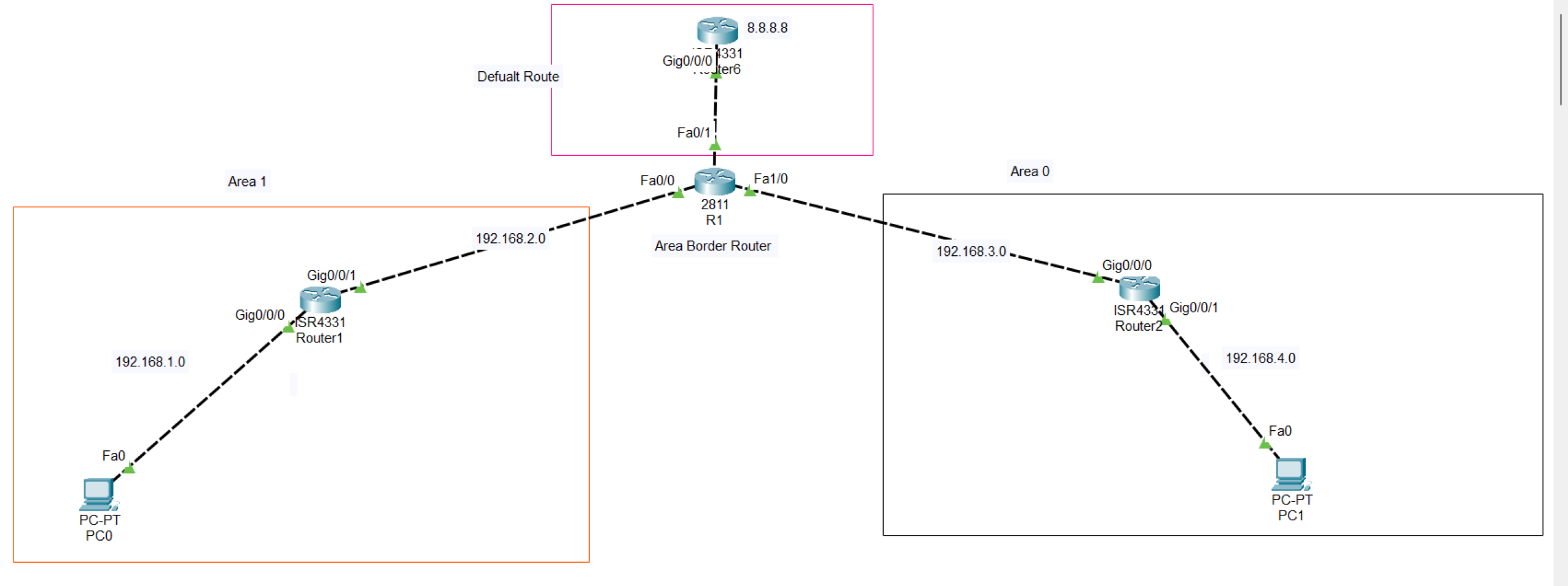
At first, adding both two areas to the R1 and setting a higher router Id to become Designated Router (RD)
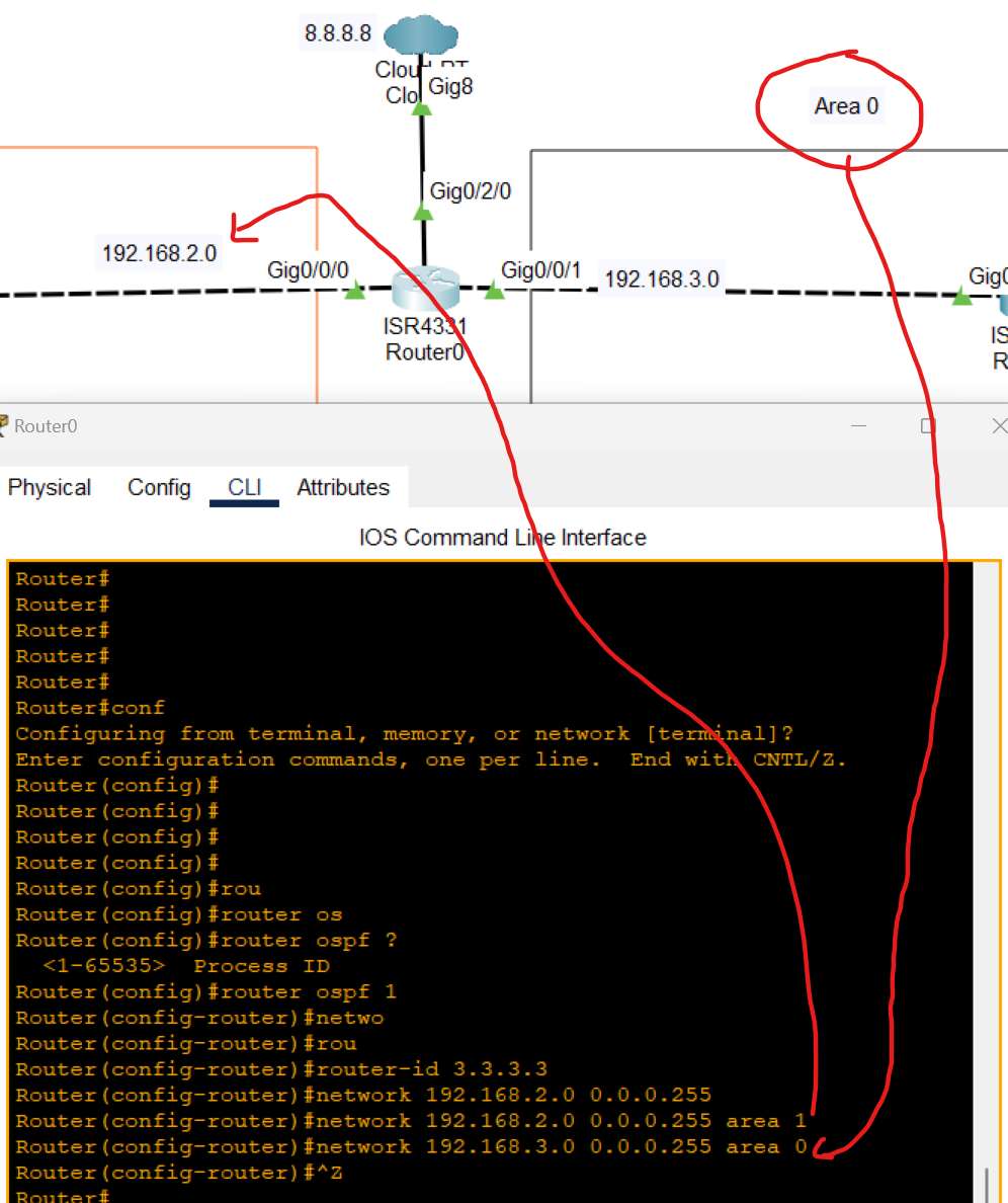
After OSPF configuration was added to the topology, a static route was applied between these two routers:
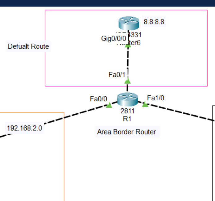
Now after adding the default route pc can't reach 8.8.8.8 defined as an internet
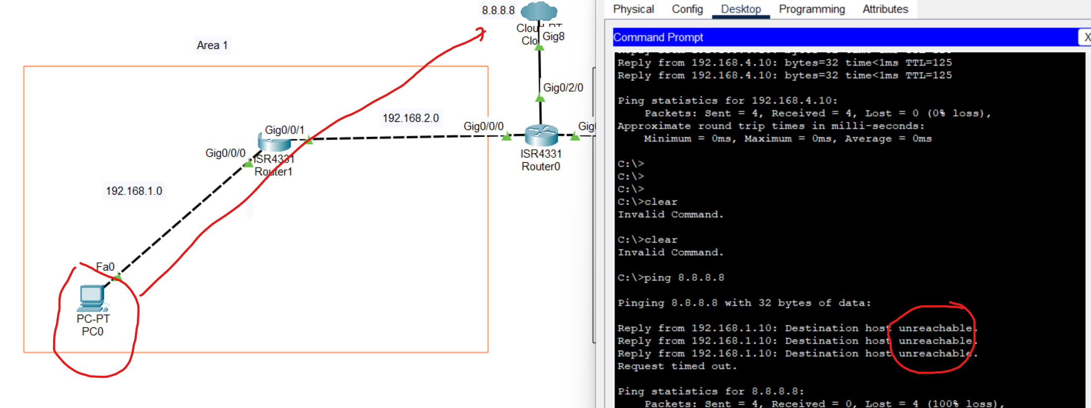
The reason for the unreachable is that the no default route add to the OSPF routing table
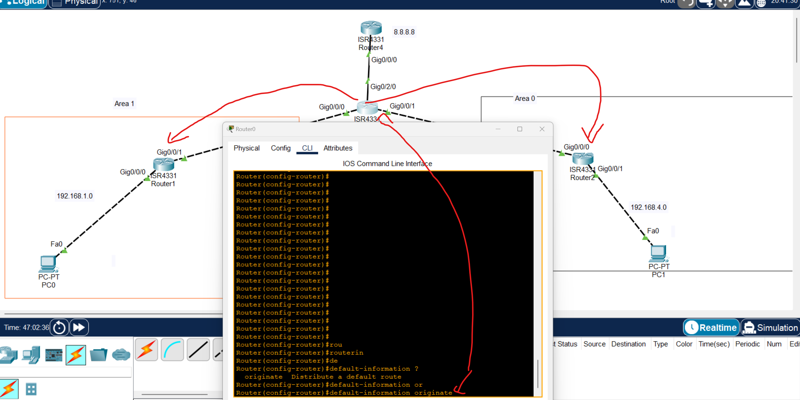
Router(config)#router ospf 1
Router(config-router)#default-information originate
use the command to automatically share the default route with other OSPF routers
Note: in packet tracer, only default-information originate working but at EVE you can use extra commands
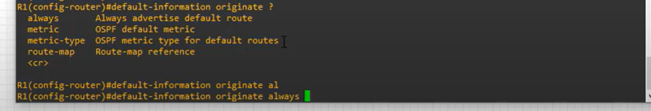
it is better to use always with this command, which always means if the connection drops the default route continuously routing the default route.
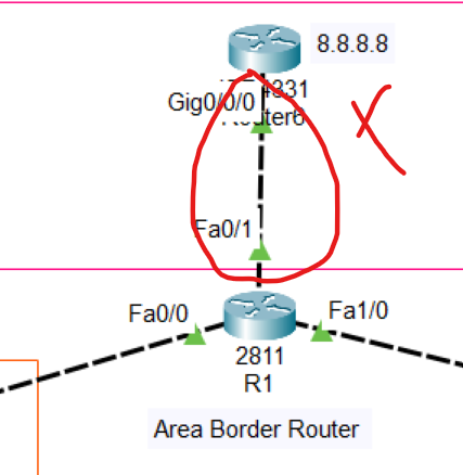
then open one of the OSPF routers you and enter show ip route
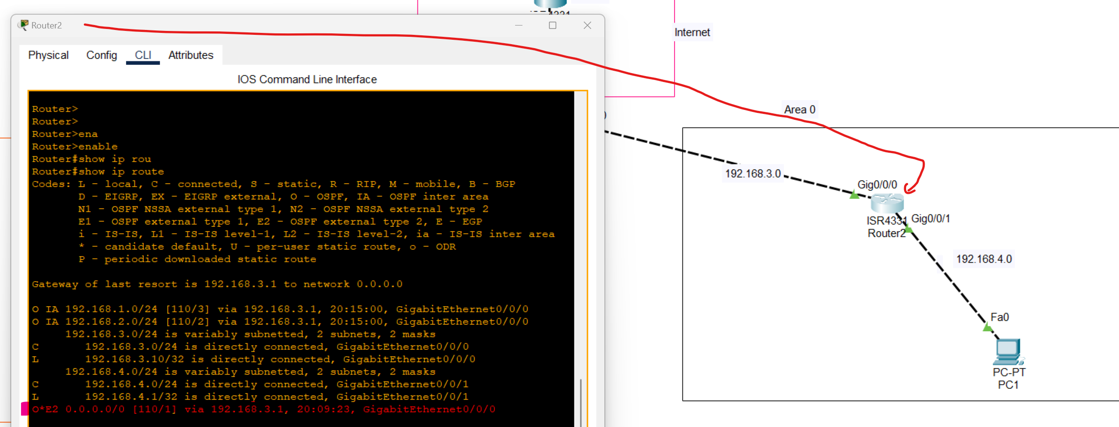
As you can see, Default Route was added to the routing table through OSPF as an external network.
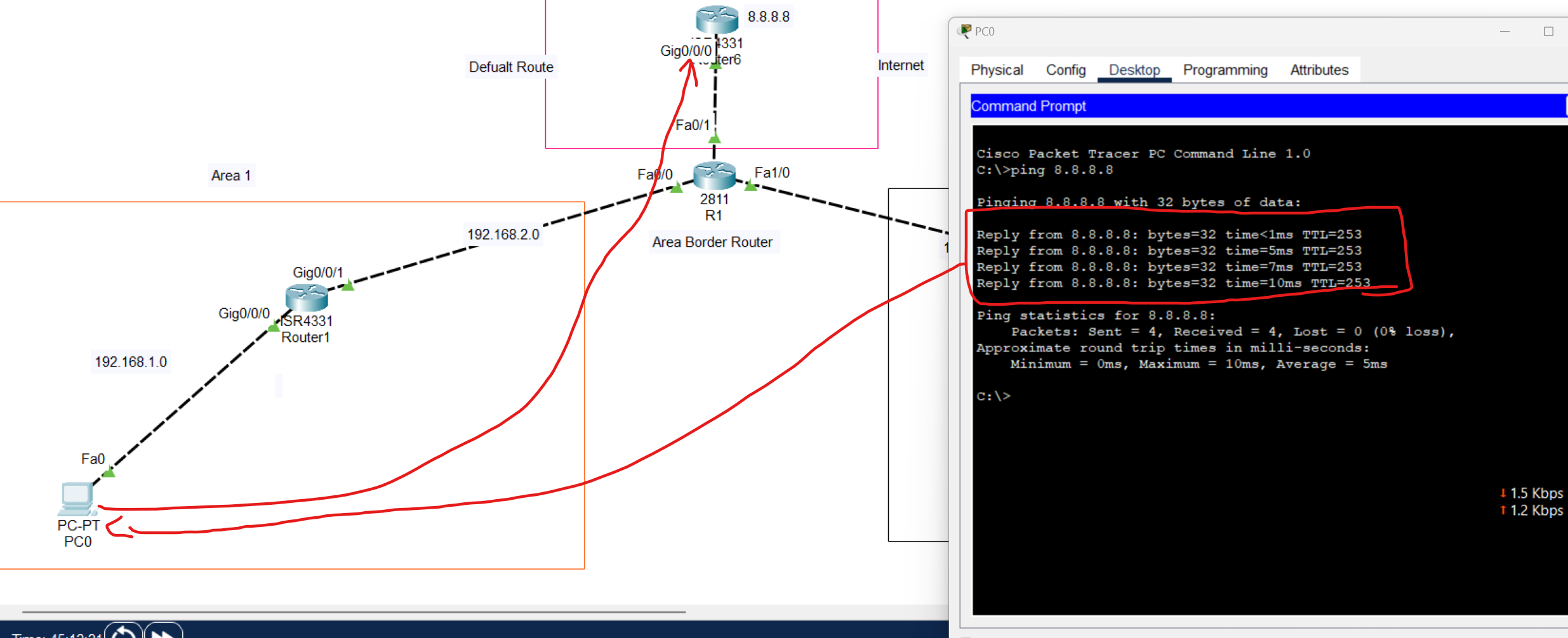
Dynamic Addressing with DHCP
Dynamic Addressing with DHCP
DHCP(Dynamic Host Configuration Protocol) is a network protocol that is used to assign unique IP address to a network devices.
DHCP is a client-server protocol. A Client DHCP is a device that configured to use DHCP Services From DHCP Server. A DHCP Server maintains a pool of available IP addresses and assign them to hosts.
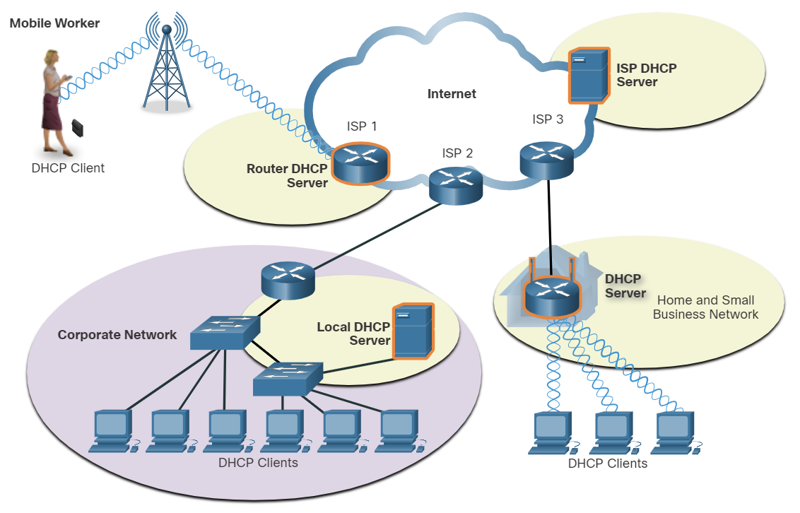
DHCP is generally the preferred method of assigning IPv4 addresses to hosts on large networks because it reduces the burden on network support staff and virtually eliminates entry errors.
Another benefit of DHCP is that an address is not permanently assigned to a host but is only leased for a period of time. If the host is powered down or taken off the network, the address is returned to the pool for reuse. This is especially useful with mobile users that can come and go on a network.
Lease time in DHCP refers to the amount of time that a DHCP server assigns an IP address to a client device. During this time, the client can use the assigned IP address without needing to request a new one. Once the lease expires, the client must either renew the lease or request a new IP address from the server.
💡 The wireless Router is both DHCP Server-Client, acts as a client to receive its IPv4 configuration from the ISP, and then acts as a DHCP server for internal hosts on the local network.
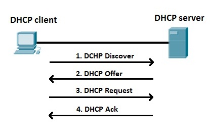
- A DHCP Client sends a (DHCP Discover) to discover DHCP servers on the LAN network. DHCP Discover is a broadcast packet with a Destination IPV4 address of 255.255.255.255 and a Destination MAC address of FF:FF:FF:FF:FF:FF.
- A DHCP Server receives the DHCP Discover packet and responds with DHCP offer packets, offering IP addressing information.
- If the client receives the DHCP offer packets from multiple DHCP servers, the first DHCP offer is accepted. the client responds by broadcasting a DHCP Request packet.
- The DHCP server approves the lease with a DHCP acknowledgment packet, which includes lease duration and other configuration information.
| Discover | Client→ Server | Broadcast |
| Offer | Server → Client | Broadcast or Unicast |
| Request | Client → Server | Broadcast |
| ACK | Server → Client | Broadcast or Unicast |
Which DHCPv4 message will a client send to accept an IPv4 address that is offered by a DHCP server?
- Broadcast DHCPREQUEST
Which three statements describe a DHCP Discover message? (Choose three.)
- The destination IP address is 255.255.255.255.
- The message comes from a client seeking an IP address.
- All hosts receive the message, but only a DHCP server replies.
DHCP Relay agent
When a device is configured as a Dynamic Host Configuration Protocol (DHCP) client, it sends a broadcast packet to discover DHCP servers on the network. Routers don't forward broadcast packets by default. If the DHCP server is on a different network from the DHCP clients, it won't receive the DHCP discover packets from the clients.
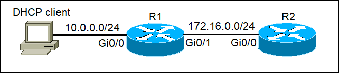
R2 can be configured as a DHCP Server, but R1 doesn't forward the DHCP Discover to the DHCP Server. We can configure R1 as a DHCP Relay Agent to forward DHCP Client packets to the DHCP Server. IP helper-address (IP of DHCP Server). Apply this command on the R1 Router interface connected to the DHCP Client
R1(config-if)#ip helper-address 172.16.0.2
💡 If your DHCP server is on another network, configure the interface closest to clients
To verify a DHCP relay agent
show ip helper-address
DHCP Server Configuration Commands
# Step 1: Exclude addresses (gateway + reserved IPs)
Router(config)# ip dhcp excluded-address 192.168.1.1 192.168.1.10

# Step 2: Create a DHCP pool
Router(config)# ip dhcp pool LAN-POOL

# Step 3: Define network and mask
Router(dhcp-config)# network 192.168.1.0 255.255.255.0

# Step 4: Define default gateway
Router(dhcp-config)# default-router 192.168.1.1

# Step 5: Define DNS server
Router(dhcp-config)# dns-server 8.8.8.8

# Step 6 (optional): Domain name
Router(dhcp-config)# domain-name ccna.local

# Step 7 (optional): Lease time (days hours minutes)
Router(dhcp-config)# lease 0 12 0
Router(dhcp-config)# exit
Router(config)# end
Router# show ip dhcp binding       # See which clients got IPs
Router# show ip dhcp pool          # Check pool statistics
Router# debug ip dhcp server events  # Debug DHCP process
DHCP Lab
DHCP Server and Relay Agent Configuration
In this scenario, we will configure a DHCP server for a company with three departments, each of which has its own subnet and connects to a departmental router.
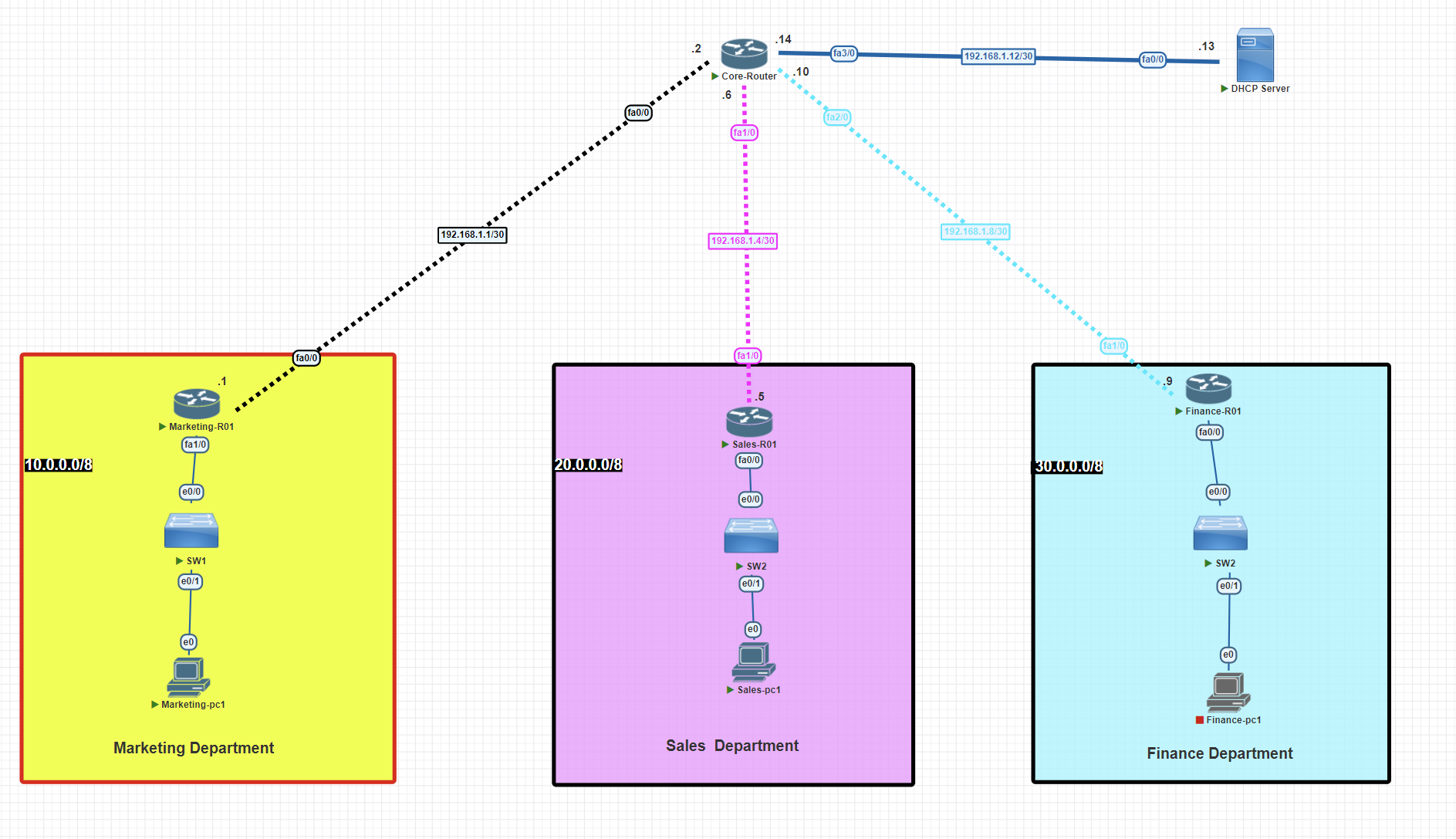
IP configuration
Core router
Router>enable
Router#configure terminal
Router(config)#hostname Core-R01
Core-R01(config)# banner motd $This Router has been set up as core router$
Core-R01(config)#int fa 1/0
Core-R01(config-if)#ip address 192.168.1.6 255.255.255.252
Core-R01(config-if)#no shutdown
Core-R01(config-if)#exit
Core-R01(config)#int fa 2/0
Core-R01(config-if)#ip address 192.168.1.10 255.255.255.252
Core-R01(config-if)#no shutdown
Core-R01(config-if)#exit
Core-R01(config)#int fa 3/0
Core-R01(config-if)#ip address 192.168.1.14 255.255.255.252
Core-R01(config-if)#no shutdown
Core-R01(config-if)#exit
Core-R01(config)#int fa 0/0
Core-R01(config-if)#ip address 192.168.1.2 255.255.255.252
Core-R01(config-if)#no shutdown
Core-R01(config-if)#exit
Marketing router
Router>enable
Router#configure terminal
Router(config)#hostname Marketing-R01
Marketing-R01(config)# banner motd $This Router has been setup for the marketing department$
Marketing-R01(config)#int fa 1/0
Marketing-R01(config-if)#ip address 10.0.0.1 255.0.0.0
Marketing-R01(config-if)#no shutdown
Marketing-R01(config-if)#exit
Marketing-R01(config)#int fa 0/0
Marketing-R01(config-if)#ip address 192.168.1.1 255.255.255.252
Marketing-R01(config-if)#no shutdown
Marketing-R01(config-if)#exit
Sales router
Router>enable
Router#configure terminal
Router(config)#hostname Sales-R01
Sales-R01(config)# banner motd $This Router has been set up for the sales department$
Sales-R01(config)#int fa 1/0
Sales-R01(config-if)#ip address 192.168.1.5 255.255.255.252
Sales-R01(config-if)#no shutdown
Sales-R01(config-if)#exit
Sales-R01(config)#int fa 0/0
Sales-R01(config-if)#ip address 20.0.0.1 255.0.0.0
Sales-R01(config-if)#no shutdown
Sales-R01(config-if)#exit
Finance router
Router>enable
Router#configure terminal
Router(config)#hostname Finance-R01
Finance-R01(config)# banner motd $This Router has been set up for the finance department$
Finance-R01(config)#int fa 1/0
Finance-R01(config-if)#ip address 192.168.1.9 255.255.255.252
Finance-R01(config-if)#no shutdown
Finance-R01(config-if)#exit
Finance-R01(config)#int fa 0/0
Finance-R01(config-if)#ip address 20.0.0.1 255.0.0.0
Finance-R01(config-if)#no shutdown
Finance-R01(config-if)#exit
Configuring RIP routing
Core router
Core-R01#conf t
Core-R01(config)#router rip
Core-R01(config-router)#network 192.168.1.0
Core-R01(config-router)#network 192.168.4.0
Core-R01(config-router)#network 192.168.8.0
Core-R01(config-router)#no auto-summary
Core-R01(config-router)#exit
Core-R01#wr
Marketing router
Marketing-R01(config)#router rip
Marketing-R01(config-router)#network 10.0.0.0
Marketing-R01(config-router)#network 192.168.1.0
Marketing-R01(config-router)#no auto-summary
Sales router
Sales-R01#conf t
Sales-R01(config)#router rip
Sales-R01(config-router)#network 192.168.1.4
Sales-R01(config-router)#network 20.0.0.0
Sales-R01(config-router)#no auto-summary
Sales-R01(config)#exit
Sales-R01#wr
Finance router
Finance-R01#conf t
Finance-R01(config)#router rip
Finance-R01(config-router)#network 192.168.1.8
Finance-R01(config-router)#network 30.0.0.0
Finance-R01(config-router)#no auto-summary
Finance-R01(config)#exit
Finance-R01#wr
Assigning a static IP to the DHCP server
Before we configure the DHCP service on the server, we have to assign a static IP address to the server.
Router>ena
Router#conf t
Router(config)#hostname DHCP-Server
DHCP-Server(config)#int fa 0/0
DHCP-Server(config-if)#ip address 192.168.1.13 255.255.255.252
DHCP-Server(config-if)#no shutdown
DHCP-Server(config)#exit
DHCP-Server#wr
Enabling and Configuring DHCP Service on the Server
Create DHCP Pools for Subnets and assign one pool to each subnet.
DHCP-Server#conf t
DHCP-Server(config)#ip dhcp pool marketing-pool
DHCP-Server(dhcp-config)#network 10.0.0.0 255.0.0.0
DHCP-Server(dhcp-config)#dns-server 8.8.8.8
DHCP-Server(dhcp-config)#domain-name rebar.it
DHCP-Server(dhcp-config)#default-router 10.0.0.1


DHCP-Server(config)# ip dhcp pool sales-pool
DHCP-Server(dhcp-config)#network 20.0.0.0 255.0.0.0
DHCP-Server(dhcp-config)#dns-server 8.8.8.8
DHCP-Server(dhcp-config)#domain-name rebar.it
DHCP-Server(dhcp-config)#default-router 20.0.0.1


DHCP-Server(config)#ip dhcp pool finance-pool
DHCP-Server(dhcp-config)#network 30.0.0.0 255.0.0.0
DHCP-Server(dhcp-config)#dns-server 8.8.8.8
DHCP-Server(dhcp-config)#domain-name rebar.it
DHCP-Server(dhcp-config)#default-router 30.0.0.1
- Each DHCP pool is usually associated with a specific subnet.
- When a client sends a DHCP request, the router or DHCP server checks the source IP subnet (if relay is used) or the incoming interface to determine which pool to use.
- The DHCP pool that matches the subnet of the incoming request is used.
Configure routers to act as DHCP relay agents.
Configure the DHCP relay agent on the router interface directly connected to the local subnet.
Marketing Router
Marketing-R01#conf t
Marketing-R01(config)#int fa 1/0
Marketing-R01(config-if)#ip helper-address 192.168.1.13
Marketing-R01(config-if)#exit
Sales Router
Sales-R01#conf t
Sales-R01(config)#int fa 0/0
Sales-R01(config-if)#ip helper-address 192.168.1.13
Sales-R01(config-if)#exit
Finance Router
Finance-R01#conf t
Finance-R01(config)#int fa 0/0
Finance-R01(config-if)#ip helper-address 192.168.1.13
Finance-R01(config-if)#exit
💡 Put the helper on the router interface that is the client’s default gateway (the access/branch router facing each department).
Verifying DHCP relay
To verify that the DHCP Service is working and each Client Received an IP address from the DHCP Pool, go to the client device and write in the terminal the command below:
C:\Users\AB>ipconfig /all
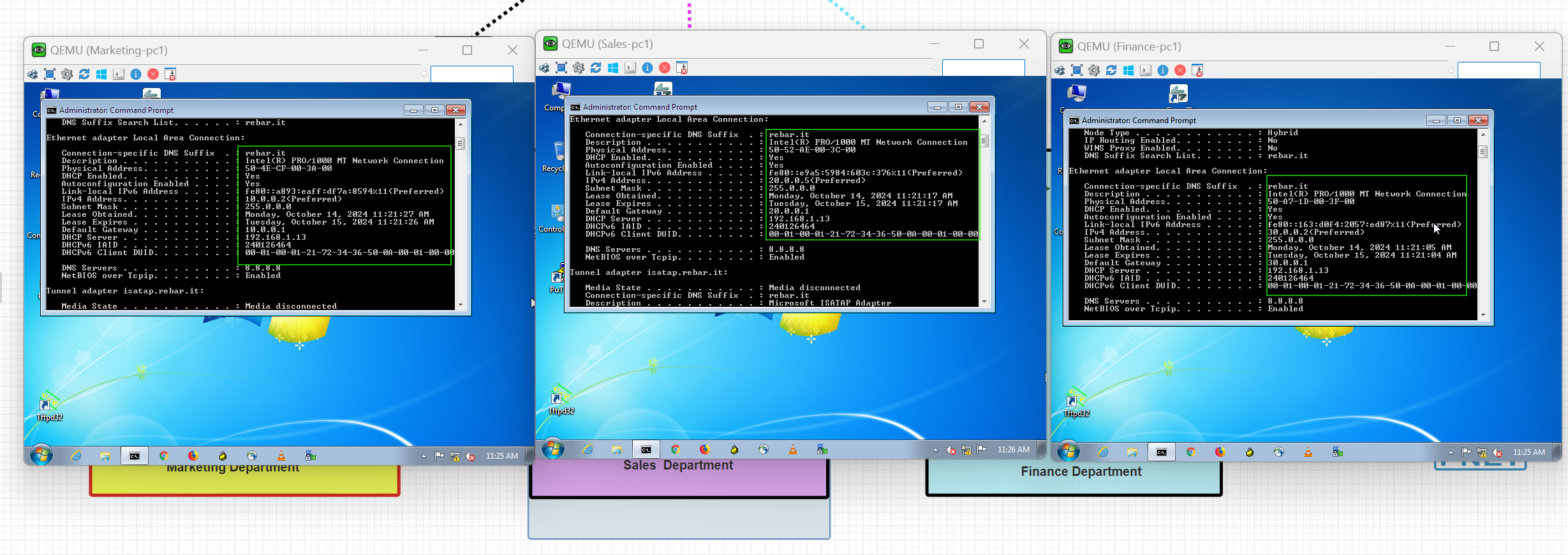
As you can see, devices from different departments or subnets have successfully obtained IP addresses from the DHCP Server.
DHCP Server Verification
To verify which IP addresses have been assigned to devices, use the following command:
DHCP-Server#show ip dhcp binding
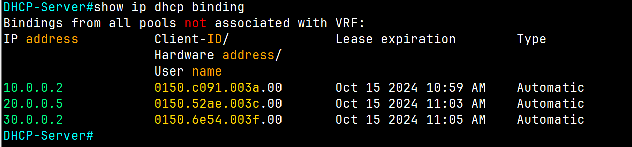
To get more information about DHCP Server, use the following command:
DHCP-Server#show ip dhcp server statistics
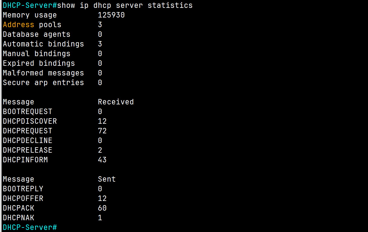
To check the DHCP Server to find out and detect any IP address conflict, use the following command:
DHCP-Server#show ip dhcp conflict
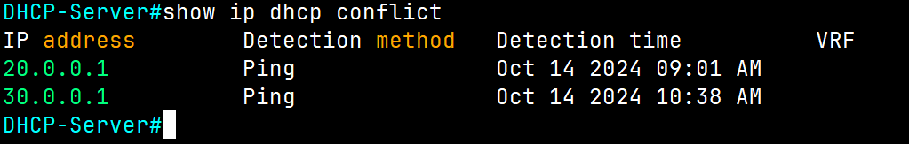
As you can see, we encountered two issues with these subnets because we're using these IP addresses statically and configured them as default gateways for each subnet.
To resolve this issue, use the following command to exclude these IP addresses from the DHCP Server Pool range:
DHCP-Server(config)# ip dhcp excluded-address (Ip of range of Ip)
DHCP-Server(config)# ip dhcp excluded-address  192.168.2.1 192.168.2.10
DHCP-Server(config)##ip dhcp excluded-address  203.0.113.1
💡 I suggest leaving at least the first of 10 IPs of each subnet for devices that require a static IP, such as printers or servers, .etc.
For our lab use the following command:
DHCP-Server(config)# ip dhcp excluded-address 20.0.0.1
DHCP-Server(config)# ip dhcp excluded-address 30.0.0.1
After choking the server again, no conflict is displayed.

DCHP Questions
D. show ip interface ✅
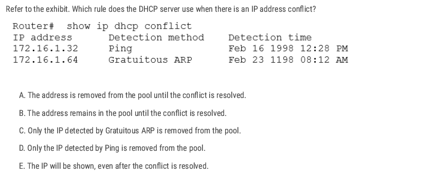
A. ✅
When a Cisco IOS DHCP server detects an IP conflict (either through ping before assigning or from a client reporting it via Gratuitous ARP), the server will:
- Mark that IP as “conflicted.”
- Remove it from the available address pool so it will not be handed out to other clients.
A spurious DHCP server is an unauthorized DHCP server operating on a network, potentially a malicious attacker trying to intercept traffic, or an accidental configuration by a user adding a rogue router.
When a DHCP client starts up, it sends a DHCPDISCOVER broadcast to look for servers.
- Legitimate and spurious (unauthorized/rogue) DHCP servers on the network will both reply with a DHCPOFFER message.
- By analyzing these DHCPOFFER messages (for example, checking the source IP/MAC address of the server), you can detect rogue DHCP servers.
- Network admins often use tools like DHCP snooping on Cisco switches to prevent unauthorized offers from being accepted.
D ✅
C D ✅
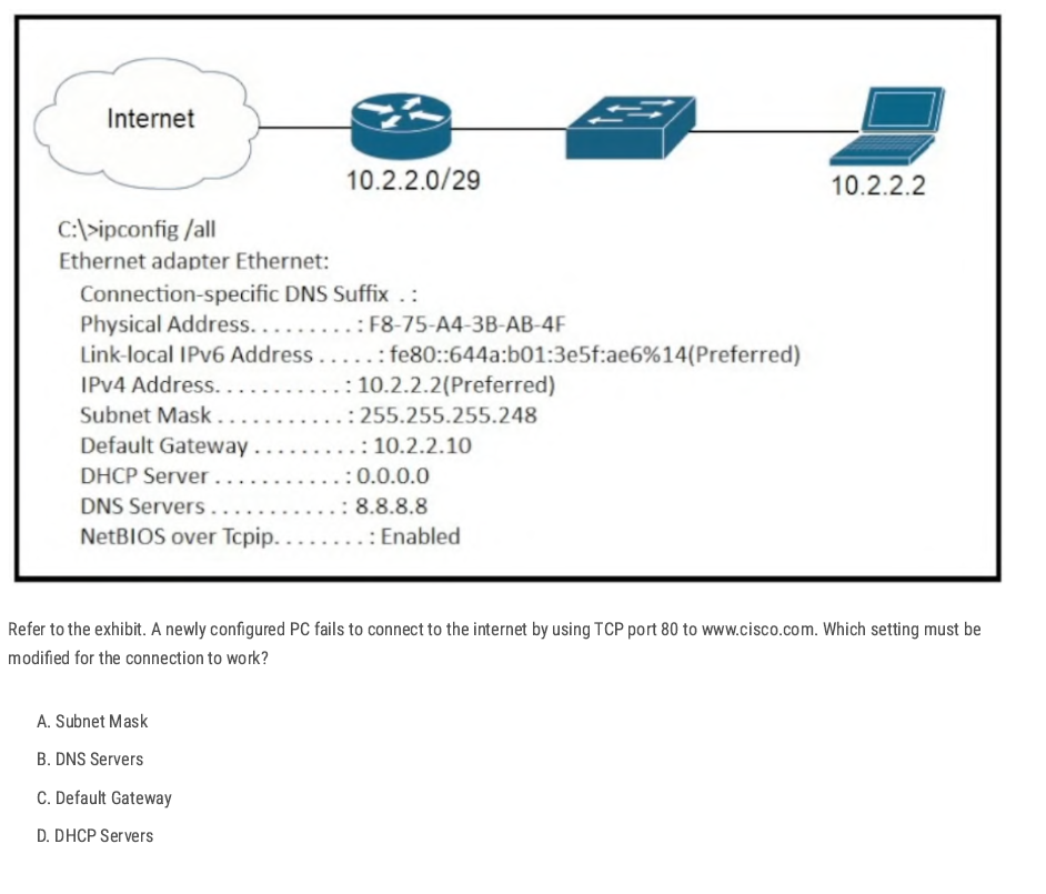
- Subnet Mask: 255.255.255.248 → valid (range:
10.2.2.1 – 10.2.2.6usable, with .0 as network, .7 as broadcast). - Default Gateway:
10.2.2.10→ ❌ incorrect, because 10.2.2.10 is outside the valid subnet (10.2.2.0/29). The gateway must be in the same subnet as the host. - DNS Servers: 8.8.8.8 → valid (Google DNS).
- DHCP Server: 0.0.0.0 → irrelevant here since the host already has an IP manually set.
C ✅
If the port connected to the workstation is blocked, it will not forward traffic, including DHCP requests, preventing the workstation from obtaining an IP address.
A ✅
B ✅
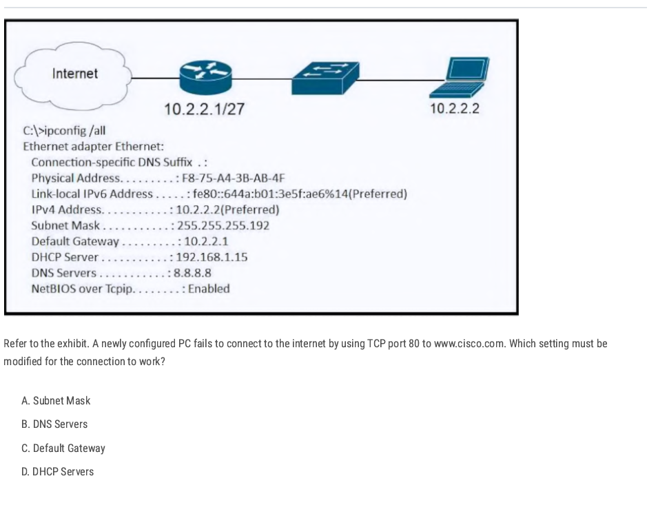
the router interface is shown as 10.2.2.1/27 (mask 255.255.255.224) while the PC is configured with 255.255.255.192 (/26). The PC and router must be in the same IP subnet mask space so the PC sends traffic for the default gateway and off-net destinations correctly.
A✅
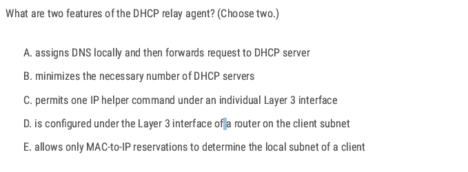
B D✅
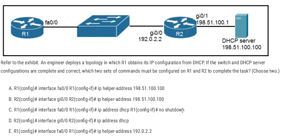
- R1 needs to request an IP address via DHCP (so
ip address dhcpis required). R2 must forward those DHCP broadcasts from R1 to the DHCP server on another network (so
ip helper-addressis required).B C✅
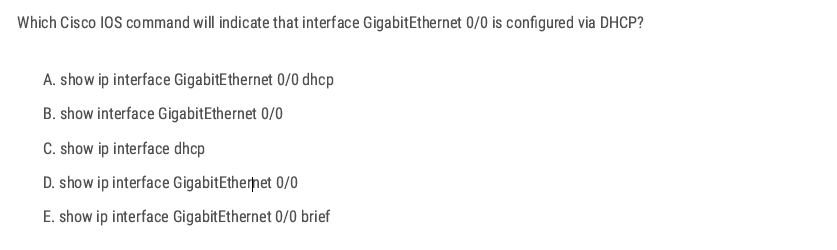
D ✅
B D ✅
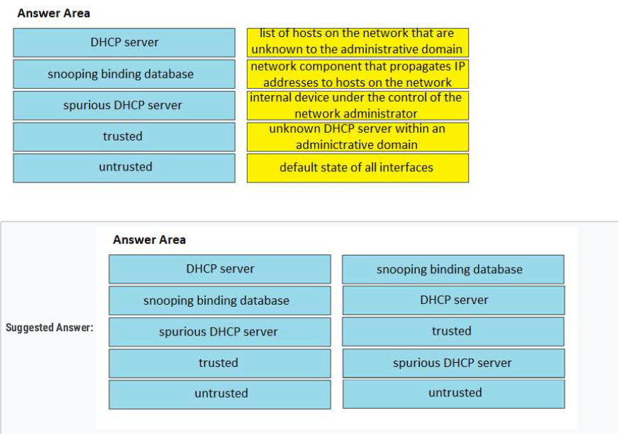
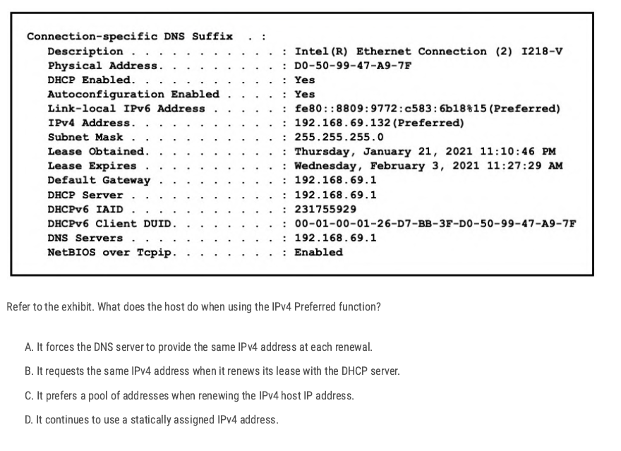
Preferred means the IP address is currently valid, usable, and active. Because the host is using DHCP and the “Preferred” state means it is currently bound to the IP address and will request the same address again during lease renewal.
B ✅
Just for information (Not CCNA Topic)
| State | Meaning | Can the host use it? | When it happens |
| Tentative | Address is being tested for duplicates (DAD in progress). | ❌ No (not yet usable). | Right after assignment (DHCP, static, or autoconfig). |
| Preferred | Address is valid and active. | ✅ Yes (full communication). | After DAD succeeds and lease is valid. |
| Deprecated | Address should not be used for new sessions, but existing ones can continue. | ⚠️ Limited (only existing connections). | Lease expired or admin marked it deprecated. |
DNS
Domain Name System DNS
DNS is a distributed hierarchical system (Root → TLD → Authoritative). used to resolve domain names into IP addresses. Instead of remembering complex IP addresses, users can type a domain name, and the DNS will find the corresponding IP address.
🌐 DNS Resolution Flow (Resolver → Name Servers)
Example: You type www.cisco.com in your browser.
1️⃣ Resolver (Client Side)
- Your resolver (inside PC/router/OS) checks:
- Local cache (has this domain been resolved recently?).
- Local hosts file (
/etc/hostsorC:\Windows\System32\drivers\etc\hosts).
- If not found, → sends a query to the configured DNS server (like 8.8.8.8).
2️⃣ Recursive Name Server (e.g., 8.8.8.8)
- Acts as your helper.
- If it doesn’t already know the answer, it goes step by step:
- Root → TLD → Authoritative server.
3️⃣ Root Name Server
- Knows where to find Top-Level Domains (TLDs) like
.com,.net,.org. - Returns: “Go ask a
.comname server.”
4️⃣ TLD Name Server (.com server)
- Knows which authoritative server holds info for
cisco.com. - Returns: “Go ask the authoritative server for
cisco.com__.”
5️⃣ Authoritative Name Server (for cisco.com)
- Has the real A record for
www.cisco.com. - Example:
72.163.4.185. - Sends back the IP to the recursive DNS server.
6️⃣ Back to the Resolver
- A recursive DNS server answers (IP) back to your resolver.
- Resolver gives it to the browser, and the connection starts.
✅ Now your PC knows that www.cisco.com = 72.163.4.185.
✅ Next time, it will use the cached entry (faster).
[PC Resolver] ---> [Recursive DNS Server (8.8.8.8)]
                       |
                       v
                 [Root Name Server]
                       |
                       v
                 [TLD Server (.com)]
                       |
                       v
         [Authoritative Server for cisco.com]
                       |
                       v
[Recursive DNS] ---> [PC Resolver] ---> [Browser gets IP]
DNS Record Types
DNS uses different record types to store various information about domains.
| Record Type | Description | Example |
| A | Maps a domain to an IPv4 address | google.com → 142.250.190.78 |
| AAAA | Maps a domain to an IPv6 address | google.com → 2607:f8b0:4005:805::200e |
| CNAME | Alias for another domain | mail.example.com → gmail.com |
| MX | Mail exchange record for emails | example.com → mail server IP |
| NS | Specifies name servers for a domain | example.com → ns1.example.com |
| TXT | Stores text information (SPF, DKIM) | Used for authentication & security |
| PTR | reverse lookup (IP → name). | 10.2.0.192.in-addr.arpa → www.example.com |
| SOA | authoritative information about a DNS zone. | example.com. IN SOA ns1.example.com. admin.example.com. ( |
2025091401 ; Serial 7200 ; Refresh (2 hours) 3600 ; Retry (1 hour) 1209600 ; Expire (14 days) 86400 ) ; Minimum TTL (1 day) |
| Feature | Recursive Query | Iterative Query |
| Who asks? | DNS client (resolver) → DNS server | DNS server → other DNS servers |
| Workload | DNS server does all the work and returns the final answer | Each DNS server gives the best possible answer it knows |
| Answer Type | Always returns the final resolved IP (or an error) | Returns either the IP or a referral to another DNS server |
| Example Flow | PC → Recursive DNS → (Root, TLD, Authoritative) → IP | Recursive DNS asks Root → gets referral → asks TLD → gets referral → asks Authoritative → gets IP |
| Traffic | More workload on DNS server, less on client | More queries across multiple DNS servers |
| Default in Clients | Used by PCs, routers, end devices | Used between DNS servers (resolver ↔ root ↔ TLD ↔ authoritative) |
DNS Configuration Cisco IOS
Enable DNS Lookup
Router(config)# ip domain-lookup
Set a Domain Name
Router(config)# ip domain-name rebar.lab
- Defines the local domain name for the device.
- Required for features like SSH key generation.
Configure DNS Servers
Router(config)# ip name-server 8.8.8.8
Router(config)# ip name-server 8.8.4.4
Static Host Mapping
Router(config)# ip host R2 192.168.1.2
Router(config)# ip host WebSrv 192.168.1.100
Creates manual hostname → IP mappings (local DNS table).
Verify DNS Resolution
Router# ping www.cisco.com
Router# traceroute www.cisco.com
Router# telnet R2
Router# show hosts
Basic Lab Configuration
R1(config)#do ping rebar.it
Translating "rebar.it"
% Unrecognized host or address, or protocol not running.
R1(config)#ip name-server 8.8.8.8  [Configure R1 to use the specified DNS server.]
R1(config)#ip domain lookup   [Enable R1 to perform DNS queries. (default)]
R1(config)#do ping rebar.it
Translating "rebar.it"...domain server (8.8.8.8) [OK]
Type escape sequence to abort.
Sending 5, 100-byte ICMP Echos to 172.217.25.110, timeout is 2 seconds:
!!!!!
Success rate is 100 percent (5/5), round-trip min/avg/max = 8/10/13 ms
Config Router As a DNS Server
R1(config)#ip dns server [Configure R1 to act as a DNS server]

R1(config)#ip host R1 192.168.0.1
R1(config)#ip host PC1 192.168.0.101
R1(config)#ip host PC2 192.168.0.102
R1(config)#ip host PC3 192.168.0.103
[Configure a list of hostname/IP address mappings.]

R1(config)#ip name-server 8.8.8.8 [Configure a DNS server that R1 will query if
the requested record isn’t in its host table.]
R1(config)#ip domain lookup [Enable R1 to perform DNS queries.]
shows the cached name/IP address mappings learned via DNS:
R1#show hosts
C ✅
D E ✅
B ✅
Normally, when you use Telnet on a Cisco device, you enter the IP address of the remote device:
R1# telnet 192.168.1.2
But what if you just want to type the hostname instead?
R1# telnet R2
For this to work, the router/switch must be able to resolve the hostname into an IP address.
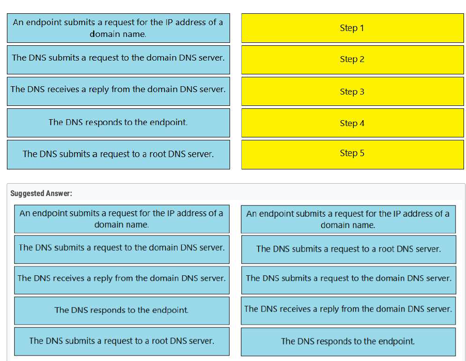
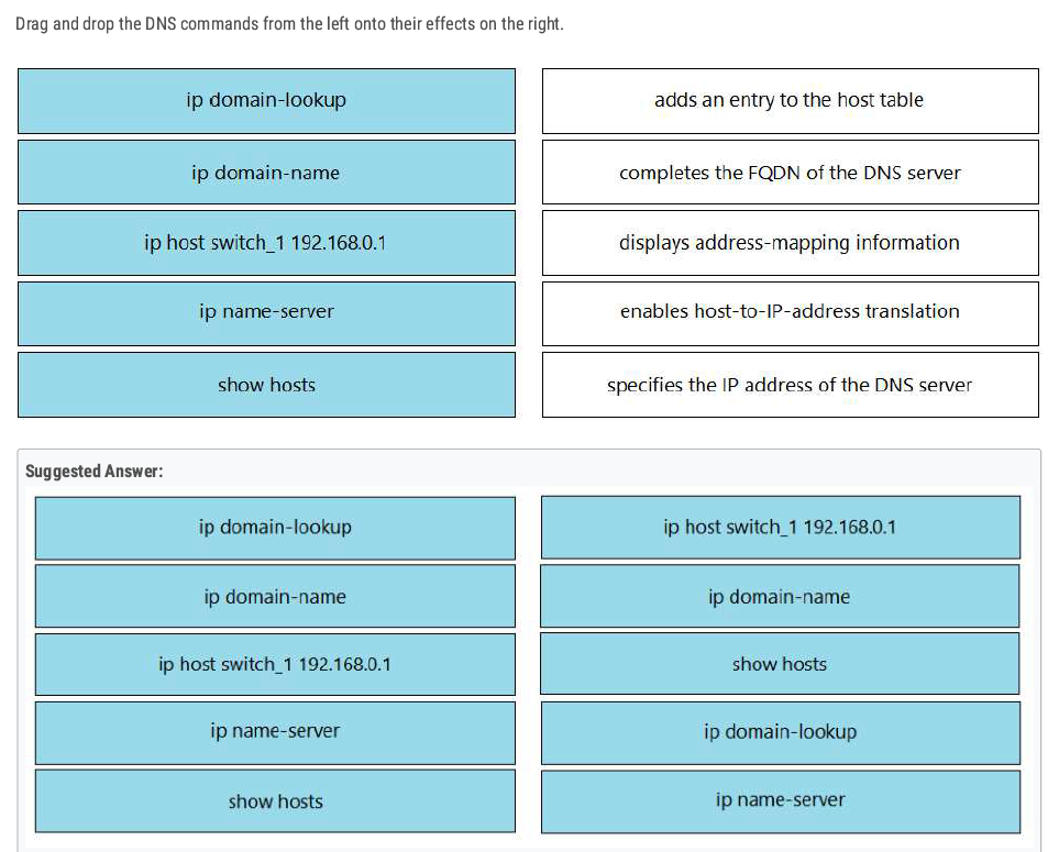
D ✅
Implementing Wireless LAN
| feature | 2.4 GHz | 5 GHz |
| Speed | Slower data transmission. | Faster data transmission. |
| Range | Longer area coverage. | Short area coverage |
| Channels | 14 Channels (only 1,6,11 are non-oversleeping). | Many non-overlapping Channels(36-165) |
Wireless technologies most frequently used in home networks are in the unlicensed 2.4 GHz and 5 GHz frequency ranges.
Wi-Fi is a wireless network to connect local area devices. It uses radio waves to send and receive data.
- The Standards we use for wireless LABs are defined in IEEE 802.11.
- Wi-Fi is a trademark of the Wi-Fi Alliance, not directly connected to IEEE.
- Wi-Fi uses two main bands (Frequency range) 2.4 GHz and 5 GHz.
- In the 2.4 GHz band, it is recommended to use channels 1,6, and 11 (non-overlapping channels).
Overlapping Channels
- In wireless networking, overlapping channels occur when multiple Wi-Fi networks operate on the same or adjacent channels, causing interference and reducing network performance. This is especially common in the 2.4 GHz band, where only three non-overlapping channels (1, 6, and 11) are available in most regions.
💡 Best Practice: Use automatic channel selection or analyze your environment with tools like Wi-Fi Analyzer to choose the best channel.
💡 Which One to Use?
- For better speed: Use 5 GHz.
- For better range & wall penetration: Use 2.4 GHz.
- For minimal interference: Prefer 5 GHz, especially in crowded areas.
| Standard | Frequencies | Max Data Rate | |
| 802.11 | 2.4 GHz | 2 Mbps | |
| 802.11 b | 2.4 GHz | 11 Mbps | |
| 802.11 a | 5 GHz | 54 Mbps | |
| 802.11 g | 2.4 GHz | 54 Mbps | |
| 802.11n | 2.4 GHz / 5 GHz | 600 Mbps | Wi-Fi 4 |
| 802.11ac | 5 GHz | 6.93 Gbps | Wi-Fi 5 |
| 802.11ax | 2.4 GHz / 5/6 GHz | 4*802.11ac | Wi-Fi 6 |
- Band: A broad range of frequencies (e.g., 2.4 GHz, 5 GHz, 6 GHz) used for wireless communication.
- Channel: A specific frequency or range within a band that devices use to communicate
RSSI
RSS standard for Received Signal Strength Indicator is a measure of the power level that an access point or wireless device receives from another device. It’s used to estimate signal strength in a wireless network.
- RSSI is usually measured in dBm(Decibels milliwatts). Value range from -100 dBm (very weak signal) to 0 dBm (Strongest possible signal).
RSSI Values:
- -30 dBm: Excellent signal (very close to the AP).
- -50 dBm: Good signal (stable connection).
- -70 dBm: Fair signal (may experience slower speeds).
- -90 dBm: Poor signal (unstable or dropped connection).
- -100 dBm: Very poor signal (no connection).
SNR
SNR(signal-to-noise ratio) measures the strength of a Wi-Fi signal compared to background noise (Interference).
It is expressed in Decibels (dB) and determines the quality of a wireless network. A higher SNR means a cleaner signal.
$SNR=Signal Strength (dBm)−Noise Level (dBm)$
Service Set
A Service Set defines a group of wireless devices that communicate using the same Wi-Fi network(SSID).
There are three main types:
- Independent Basic Service Set (IBSS).
- Infrastructure
- Mesh
Independent Basic Service Set (IBSS)
Independent Basic Service Set (IBSS) is a wireless network in which two or more wireless devices are connected directly without using an Access Point(AP).
- Also called an Ad hoc network.
Basic Service Set (BSS)
A BSS (Basic Service Set) is a kind of infrastructure Service Set in which clients connect to each other via an AP(Access Point), but not directly to each other.
- A BSSID (Basic Service Set ID) uniquely identifies the AP. The BSSID is the MAC address of the AP’s radio.
- Service set identifier (SSID): This is a human-readable, non-unique identifier used by the AP to advertise its wireless service.
- Other APs can use the same SSID, but not the same BSSID.
- Wireless devices request to associate with the BSS. Wireless devices that are associated with the BSS are called “Client” or “Station”.
- The area around an AP where its signal is usable is called a BSA (Basic Service Area).
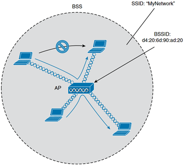
Extended Service Set (ESS)
A Wi-Fi network that consists of multiple Access Points (APs) working together under the same SSID to provide a wider coverage and support roaming between APs.
- Each BSS uses the same SSID.
- Each BSS has a unique BSSID.
- Each BSS uses a different channel to avoid interference.
- Clients can pass between APs without having to reconnect.
- The BSAs should overlap about 10-15%.
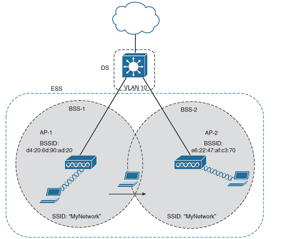
Mesh Basic Service Set (MBSS)
A Mesh Basic Service Set (MBSS) is a wireless mesh network where multiple Access Points (APs) (called Mesh Nodes) communicate with each other without a wired backbone. It is used to provide large coverage and self-healing capabilities.
- At least one AP is connected to the wired network, it is called RAP (Root Access Point).
- No wired connections between nodes—only wireless links.
- The other APs are called MAPs(Mesh Access Points).
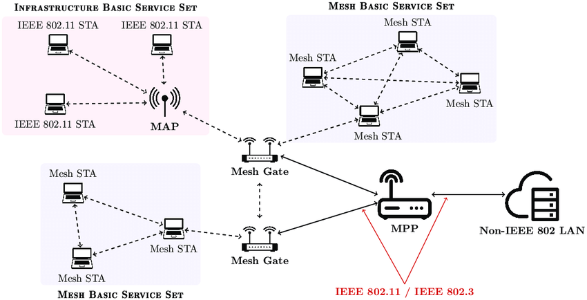
Distribution System
Refers to the upstream wired Ethernet as the distribution system (DS) for wireless BSS.
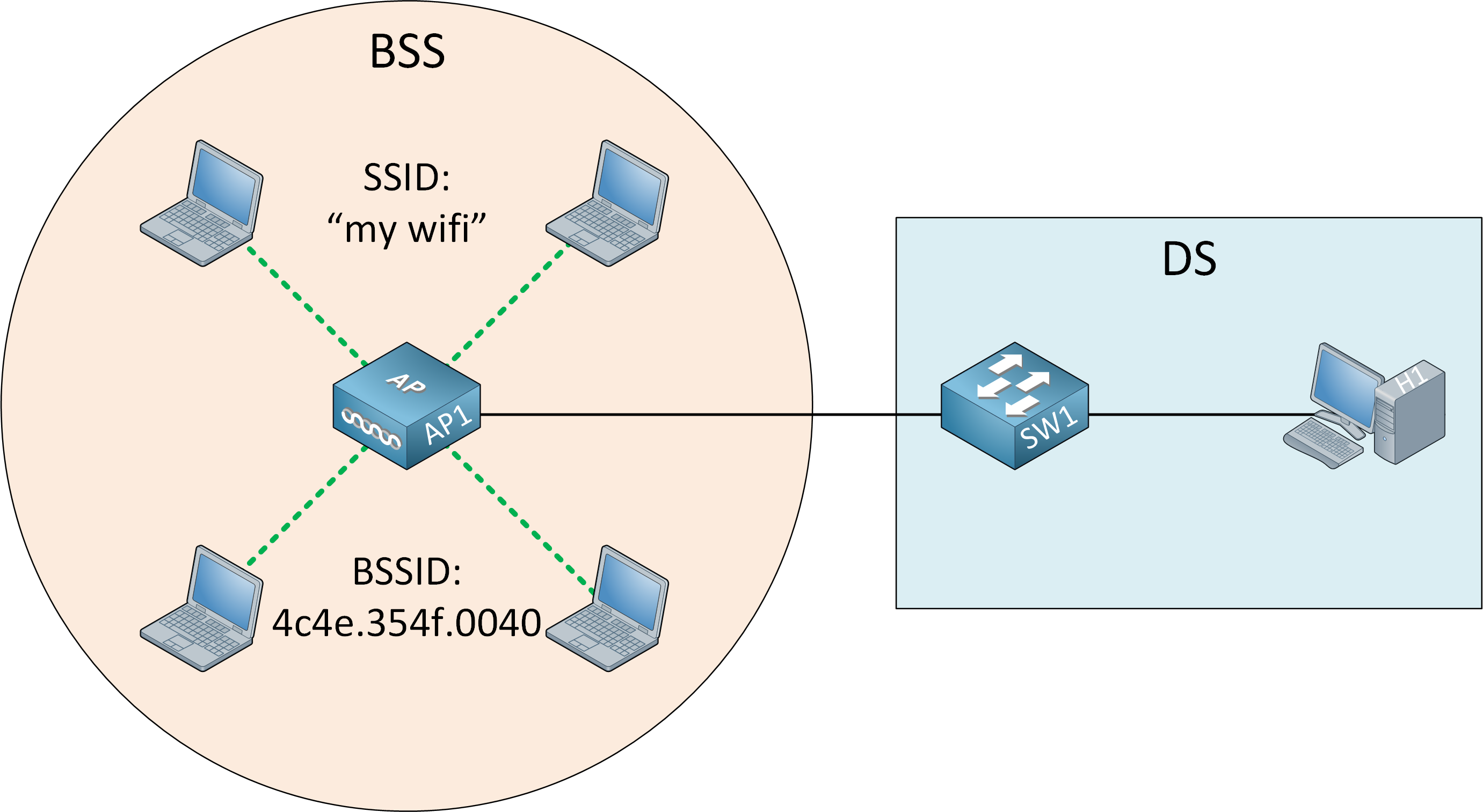
WorkGroup Bridge (WGB)
WorkGroup Bridge(WGB) is a Wi-Fi client device that connects a wired device to a wireless network by acting as a bridge between an Ethernet network and a Wi-Fi access Point (AP).
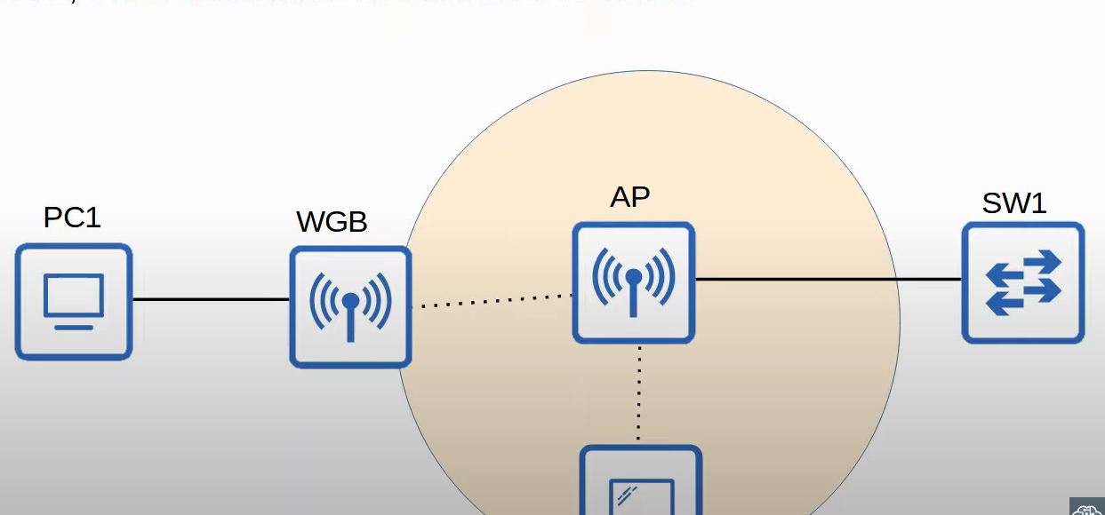
Outdoor Bridge
An outdoor Bridge is a wireless connection between two or more locations, used to extend a network over long distances without cables. It is commonly used for connection building and remote offices. The connection can be point-to-point or point-to-multipoint.
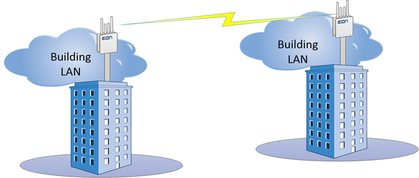
Wireless Architectures
There are three main wireless AP deployment methods:
- Autonomous
- Lightweight
- Cloud-Based
Autonomous Architecture
An Autonomous AP is a self-contained access point that operates independently, without requiring a centralized wireless controller. it is commonly used in small networks when a few APs are needed.
- Self-Managed, no need for a separate controller.
- Each AP has its configuration(SSID, Security, QoS Rules, etc.).
Lightweight Architecture
A Lightweight Access Point(LWAP) is a Wi-Fi access point that relies on a Wireless LAN Controller(WLC) for configuration, management, and traffic handling. Unlike autonomous APs, LWAPs do not function independently and require a centralized controller.
- Lightweight APs handle real-time operations like transmitting/receiving RF traffic, and encrypting/decrypting traffic.
- Other functions are carried out by a WLC, for example, RF management, Security/QoS management, client authentication, client association/roaming management, etc.
- This is called split-MAC architecture.
- The WLC is used to centrally configure the Lightweight APs.
- The WLC and Lightweight use a protocol called CAPWAP(Control And Provisioning Of Wireless Access Points) to communicate.
Two tunnels are created between each AP and WLC:
- Control tunnel (UDP port 5246): this tunnel is used to configure the APs , and control/manage the operation. All traffic in this tunnel is encrypted by default.
- Data tunnel (UDP port 5247): all traffic from wireless clients is sent through this tunnel to the WLC (It does not go directly to the wired network).
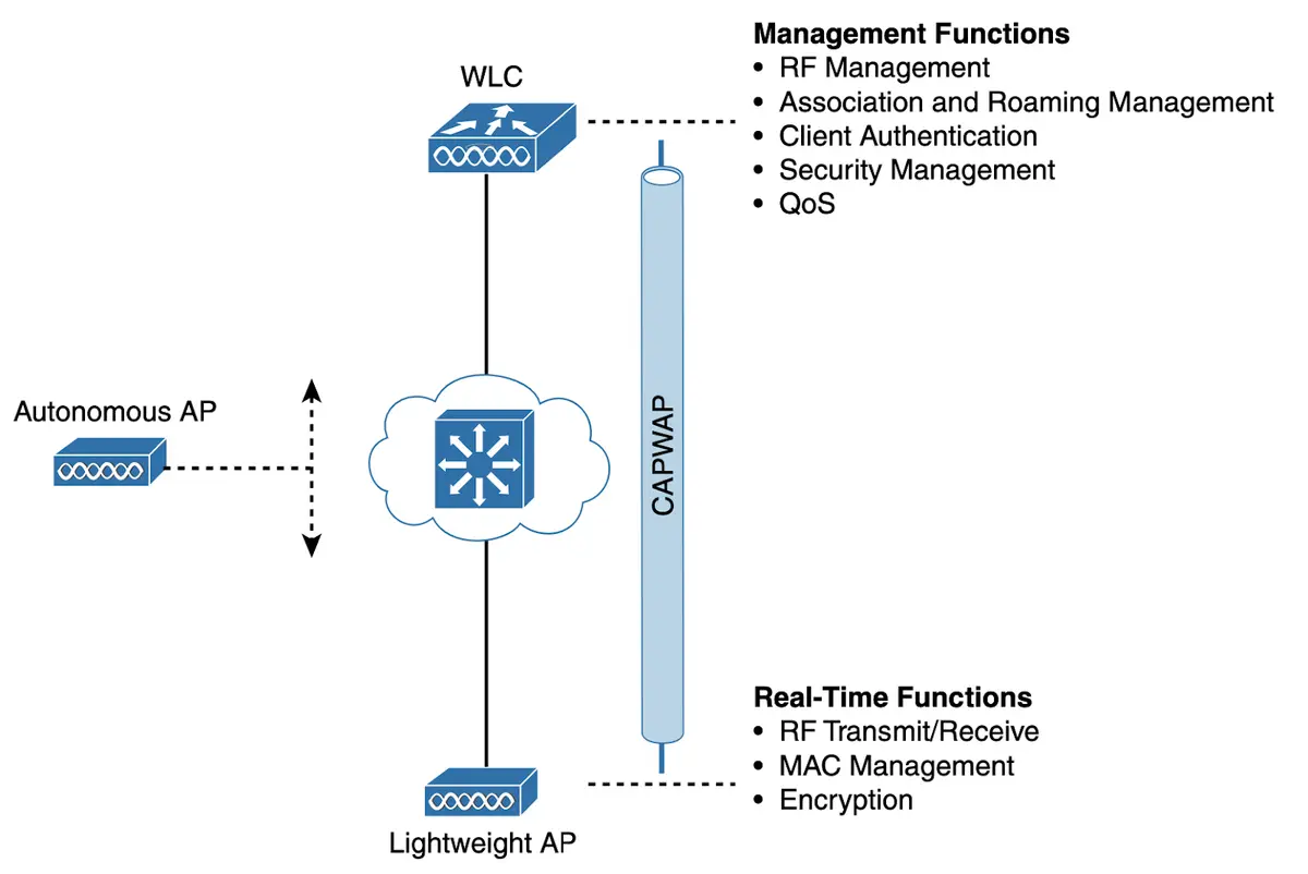
- Controlled Access Point works as the client of the Wireless LAN Controller (WLC). Technically a controlled access point is known as the Lightweight Access Point (LWAP). The WLC based on the security configuration, makes the decision whether the received frame should be forwarded or discarded.
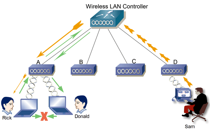
An access point controller (AP controller) is a device that manages and controls wireless access points (APs) in a wireless network. It allows for centralized management of APs, which can simplify configuration and troubleshooting. AP controllers can also provide features such as load balancing, roaming, and security.
Here are some of the benefits of using an access point controller
- Centralized management: AP controllers allow for centralized management of APs, which can simplify configuration and troubleshooting.
- Improved performance: AP controllers can improve performance by load-balancing traffic across multiple APs and providing roaming.
- Enhanced security: AP controllers can provide enhanced security by encrypting traffic and authenticating users.
- Scalability: AP controllers can scale to accommodate larger networks.
WLC Ports and Interfaces
- WLC Ports are physical ports that cables connect to.
- WLC Interfaces are the logical interfaces within the WLC(ie. SVIs on a switch).
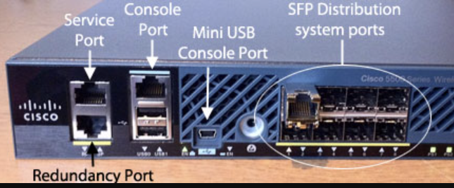
Service Port: Used for out-of-band management(not user traffic).
- Management access via SSH, HTTP(S), or Telnet.
- Software upgrades and troubleshooting.
- Cannot be used for normal wireless traffic.
Distribution Port/ Network Port: Connect to a switch (trunk mode) for AP traffic and VLAN communication.
Redundancy Port: connects two WLCs for high availability.
Console Port: This is a stand console port, either RJ45 or USB.
How the Internet Flows Through a WLC Network
💡 Internet → Router/Firewall → Core Switch → WLC (via Distribution Ports) → Access Points → Wireless Clients
Cloud-Based Architecture
A Cloud-Based Architecture in wireless networking refers to a system where Wi-Fi Access Points (APs) are managed remotely through a cloud controller, instead of a traditional on-premises Wireless LAN Controller (WLC).
Cisco Meraki – Cloud-managed networking for enterprises.
How Cloud-Based Architecture Works:
1️⃣ Access Points (APs) connect to the internet and communicate with a cloud-based controller.
2️⃣ The cloud controller manages all APs centrally from a web-based dashboard.
3️⃣ Network admins configure, monitor, and troubleshoot Wi-Fi from anywhere.
4️⃣ APs receive real-time updates, security patches, and configurations from the cloud
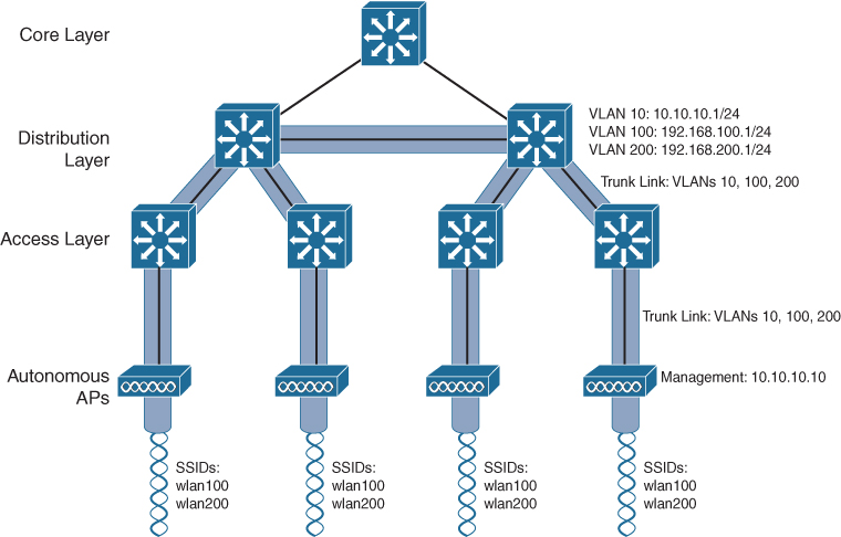
Access Point
- An access point is a device that allows multiple wireless devices to connect**.** connects various devices in a single or multiple wired LAN network, and an access point connects various wireless devices in a single or multiple wireless network.
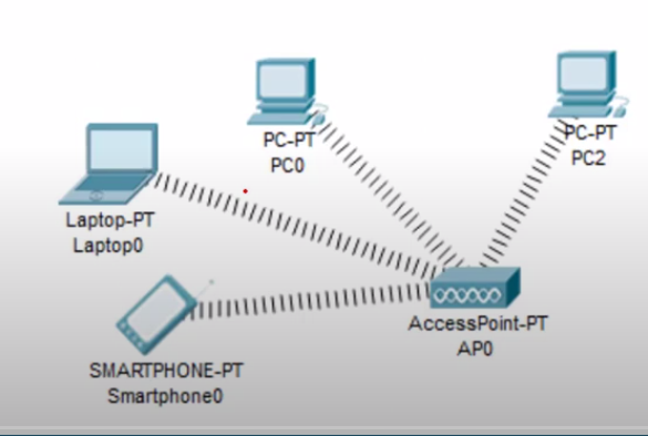
Types of Access Points
- Standalone access Point. (Heavyweight or Fat).
- Multifunction Access Point.
- Controlled Access Point(Lightweight).
Standalone Access Point
- A standalone access point provides the same functionality in a wireless network that a switch or hub provides in a wired network. It provides connectivity between the different wireless devices. It accepts a frame from the connected device and, based on its physical address, forwards it to the destination device.
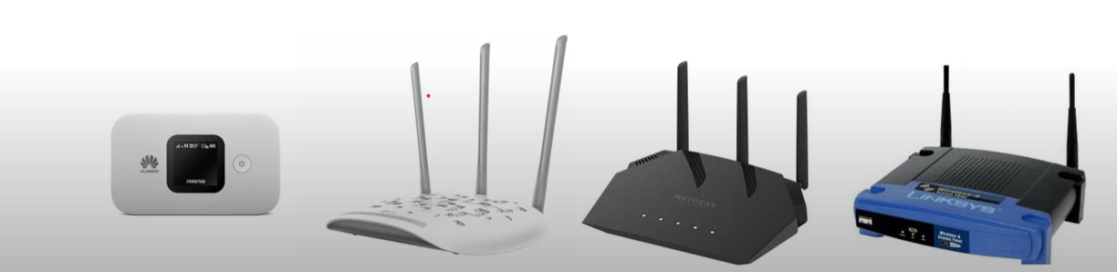
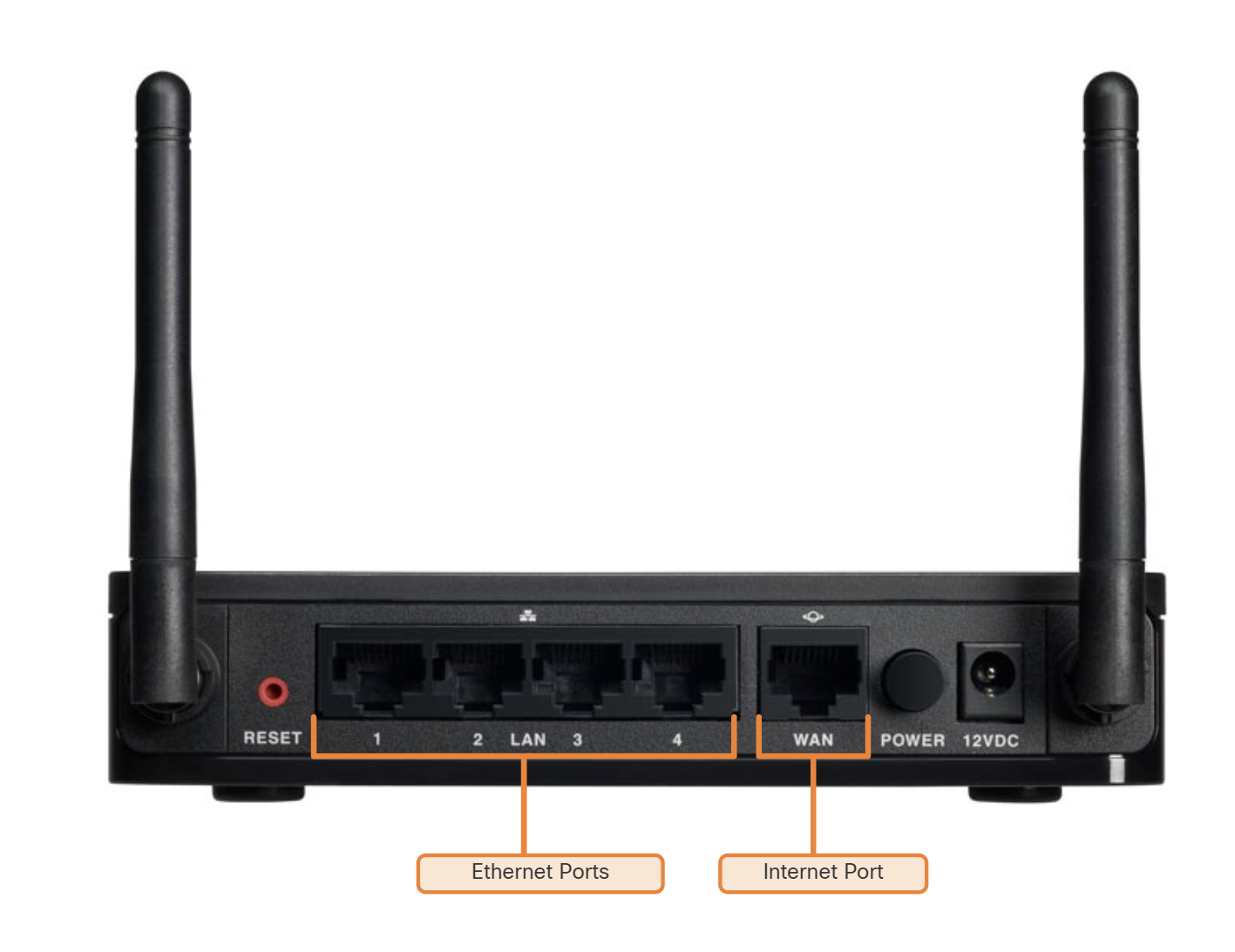
Ethernet Ports: These ports connect to the internal switch portion of the router. These ports are usually labelled “Ethernet” or “LAN”, as shown in the figure. All devices connected to the switch ports are on the same local network.
Internet Port: This port is used to connect the device to another network. The internet port connects the router to a network different from the Ethernet ports. This port is often used to connect to the cable or DSL modem in order to access the internet.
Multifunction Access Point
- A multifunction access point is the same combination of two or more devices. in this combination, an additional device or devices are merged with the access point to provide the additionalities along with the existing functionality of the access point.
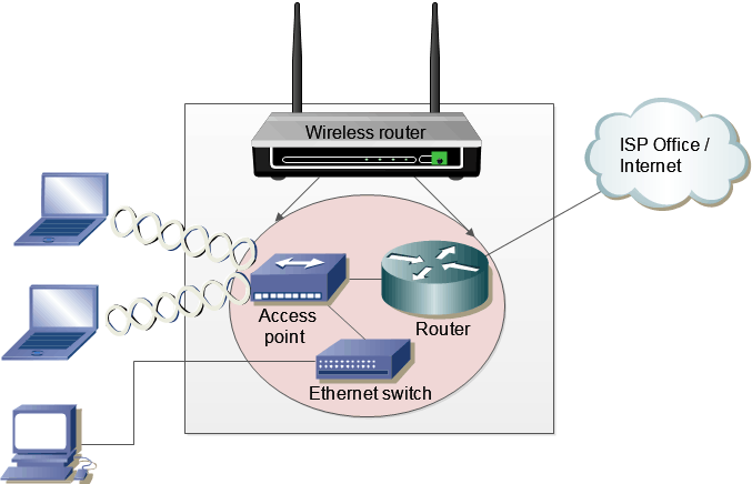
Why it is called a Multifunction access point?
It works as A router routing local networks to other networks like Internet Networks.
it is used as an access point connecting all wireless devices together
It can be used as a switch because of having Ethernet ports.
Wireless Lan Controller
- first, make a connection between Pc and WLC devices, then login to the WLC Through browser 192.168.1.1 and do the basic configuration
- We Add a DHCP Server to assign IP to each access point, it is an easy way to assign IP to each AP instead of Manually.
- Create SSID for each WLAN In WLC Web-based interface.
- Then create a group for AP Devices, all access points grouped by SSID
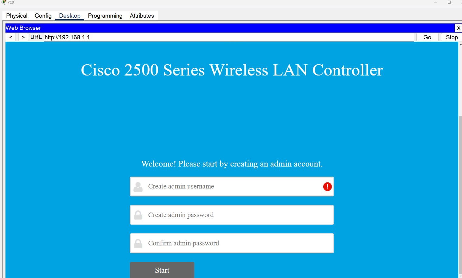
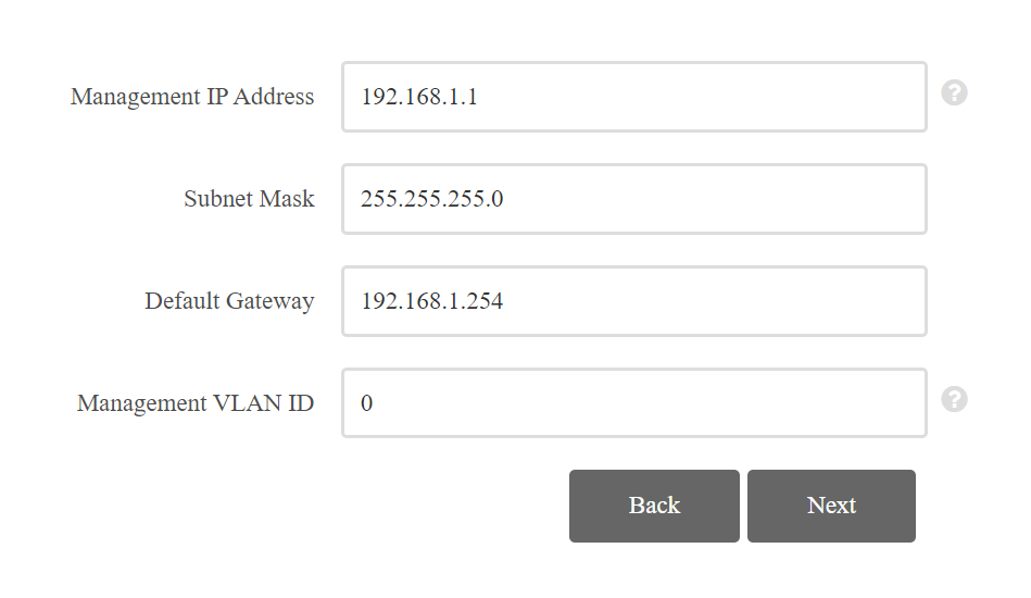
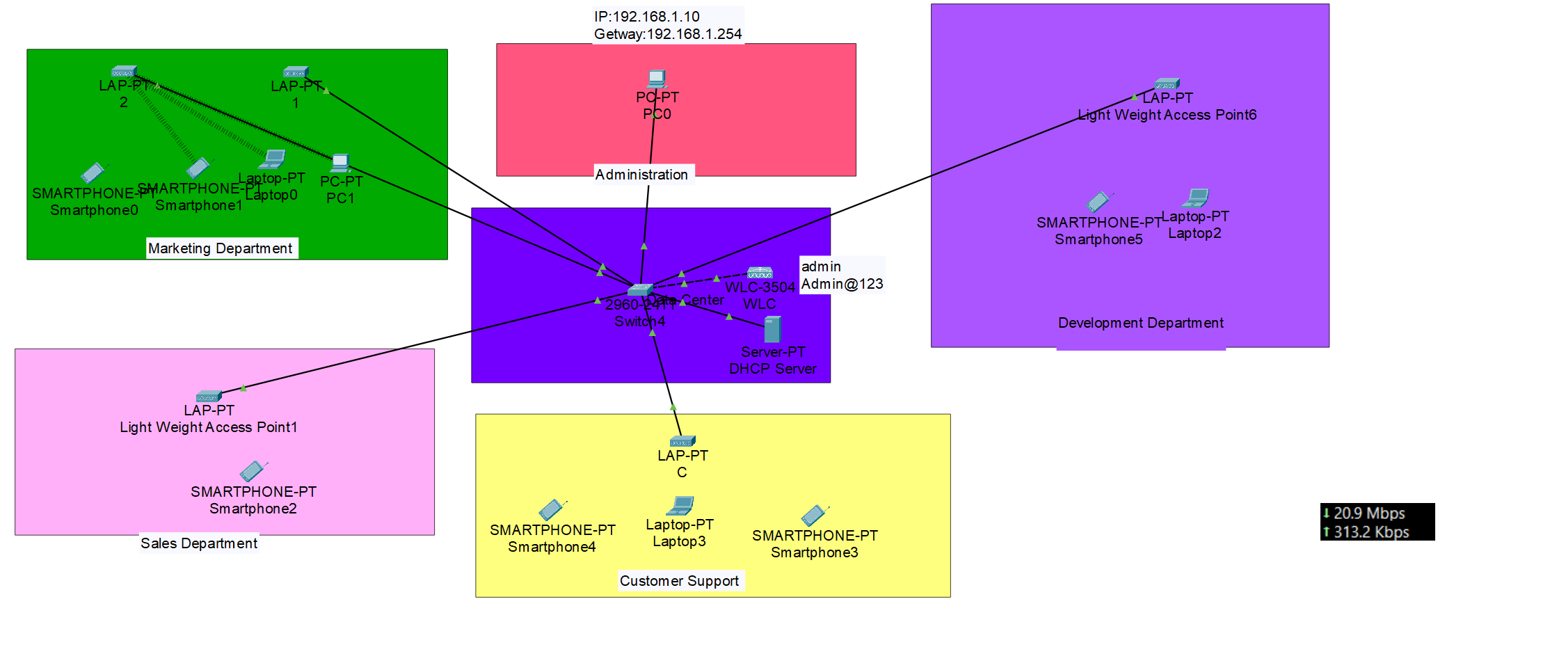
Wireless Security
Open Authentication
Open Authentication (Open System Authentication) is the simplest form of Wi-Fi authentication where any device can connect to the wireless network without requiring a password or credentials. The problem with this method is that the SSID is typically broadcast and if it is not, it can be easy to figure out with passive capturing techniques. Used in public Wi-Fi hotspots, cafes, and guest networks.
802.1x/EAP
Extensible Authentication Protocol (EAP) is the most widely used authentication method in enterprises. It relies on an authentication server to verify user credentials through various authentication mechanisms.
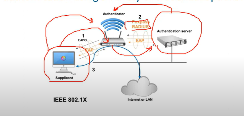
- Supplicant: The device trying to connect (mobile, laptop…etc.)
- Authenticator: The network device enforcing authentication. forwards the request to the RADIUS server using EAP.
- Authentication Server: Usually Radius Server verifies credentials and grants or denies network access.
Types of 802.1x/EAP
- LEAP(Lightweight Extensible Authentication Protocol), is an EAP authentication type used primarily in Cisco Aironet * WLANs, It encrypts data transmissions using dynamically generated WEP keys and supports mutual authentications.
- EAP-FAST(Flexible Authentication via Secure Tunneling) is used for enterprises that can’t enforce a strong password policy and don’t want to deploy certifications for authentication.
- PEAP(Protected Extensible Authentication Protocol) provides a method to transport securely authentication data, including legacy password-based-protocols, via 802.11 Wi-Fi networks(deployed by MS and Cisco)
💡 for example, in hotels, you can’t use strong passwords or deploy a certification on end-user devices.
- EAP-TLS(Transport Level Security), while very secure, requires client certificates to be installed on each WI-FI workstation. Maintenance of a PKI infrastructure requires additional administrative expertise and time in addition to that of maintaining the WLAN itself.
Wireless Privacy and Integrity Methods
WEP (Wireless Equivalent Privacy)
- The first widely used standard for wireless LANs was 802.11(prime), this included the wired Equivalent Privacy(WEP) algorithm which was used for security. WEP utilizes RC4 for encryption and has been appreciated because of vulnerabilities that can be used to find the security keys
WPA(Wi-Fi Protected Access)
- In response to the vulnerabilities found in WEP, Wi-Fi Protected Access(WPA) was defined. WPA utilizes the Temporal Key Integration Protocol(TKIP), which utilizes dynamic keys that were not supported with WEP and RC4 for encryption. The TKIP method used with WPA was utilized until vulnerabilities were found in TKIP. These vulnerabilities center on the fact that TKIP uses the same mechanisms that WEP does, which allow similar attacks.
WPA 2
- In response to the vulnerabilities in WPA/TKIP, The IEE 802.11i standard was defined and implemented, the IEEE 802.11i standard is also referred to as WPA2, WPA2 replaced TKIP with Counter Mode with Cipher Block Chaining Message Authentication Code Protocol (CCMP) which is based on Advanced Encryption Standard(AES) AES-128, it is common for the WPA2 encryption method to be referred to as AES, There are on easy methods that have been found to break AES.
WPA 3
- The WPA 3 provides new features for personal and enterprise use, such as 256-bit Galois/Counter Mode Protocol (GCMP-256), 384-bit Hash Message Authentication Mode(HMAM), and 256-bit Broadcast/Multicast Integrity Protocol (BIP-GMAC-256). WPA 3 also supports security measures such as perfect forward secrecy.
The Wi-Fi Alliance has developed WPA-WPA2-WPA3, all of which support two authentication modes:
- Personal mode: Used for home and small office networks, A pre-shared key (PSK) is used for authentication no special authentication server is required.
- Enterprise Mode: Used for enterprise and large networks require a remote authentication server (RADIUS SERVER) for user authentication. The user must authenticate using the 802.1x standard which uses Extensible Authentication Protocol for authentication.
💡 Which organization is responsible for testing wireless LAN devices?
Wi-Fi Alliance
Wi-Fi Alliance
Encryption Methods
- RC4(40-bit) (**Rivest Cipher 4**) is a stream cipher. while it is remarkable for its simplicity and speed in software, multiple vulnerabilities have been discovered in RC4, rendering it insecure.
- Temporal Key Integrity Protocol (**TKIP) is a wireless network security protocol of IEEE 802.11. Assigning a unique 48-bit sequencing number to each packet using 128-bit encryption keys and 64-bit authentication keys.**
- AES:(AES-CCMP): This algorithm provides enhanced security over TKIP and is the only encryption algorithm supported by the 802.11i standard (the standard that introduced WPA2).
- AES-GCMP-256: Galois Counter Mode Protocol (GCMP) is supported by 802.11ac, is more efficient than AES-CCMP, and provides better performance for wireless clients. AES-GCMP-256 uses 256-bit AES encryption keys.
Standard Channel: Specifies the channel over which communication will occur. By default, this is set to Auto to allow the access point (AP) to determine the optimum channel to use.
A mixed-mode wireless network environment can include devices that use any of the existing Wi-Fi standards. This environment provides easy access for older devices that need a wireless connection but do not support the latest standards.
What is the difference between 5G and 5 GHz? (Just For Information, Not CCNA topic)
- 5G refers to the fifth generation of cellular network technology. It uses radio waves in the 3.5GHz to 3.7GHz range to transmit data. 5G offers much faster speeds and lower latency than previous cellular generations, such as 4G LTE**.**
- 5GHz refers to a frequency band that is used by some Wi-Fi systems. It is located in the 5.1GHz to 5.8GHz range and offers faster speeds than the 2.4GHz Wi-Fi band. However, 5GHz has a shorter range and is more susceptible to interference.
| Feature | 5G | 5GHz |
| Technology | Cellular network | Wi-Fi |
| Frequency range | 3.5GHz to 3.7GHz | 5.1GHz to 5.8GHz |
| Typical speeds | Up to 20Gbps | Up to 1Gbps |
| Range | Shorter | Longer |
| Susceptibility to interference | Less susceptible | More susceptible |
💡 The wireless technologies most frequently used in home networks are in the unlicensed 2.4 GHz and 5 GHz frequency ranges.
WLAN CCNA Questions
CPU ACL → Blocks or allows management access (SSH, HTTPS, SNMP) to the WLC from specific networks. B✅
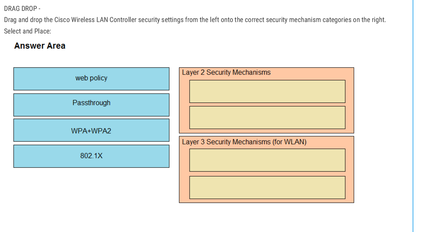
Layer 2 Security Mechanisms
- WPA + WPA2
- 802.1X
👉 Layer 2 deals with encryption and authentication before a client can join the WLAN.
Layer 3 Security Mechanisms (for WLAN)
- Web policy
- Passthrough
👉 Because Layer 3 mechanisms kick in after association, often for user authentication or web redirection.
The Passive Client feature on the Cisco Wireless LAN Controller (WLC) ensures that devices with static IPs (like printers, scanners, or IoT devices) can still associate and pass traffic correctly.
C✅
Discovery request — because that’s the first message an AP sends to the WLC AP-Manager interface during the join process. D✅
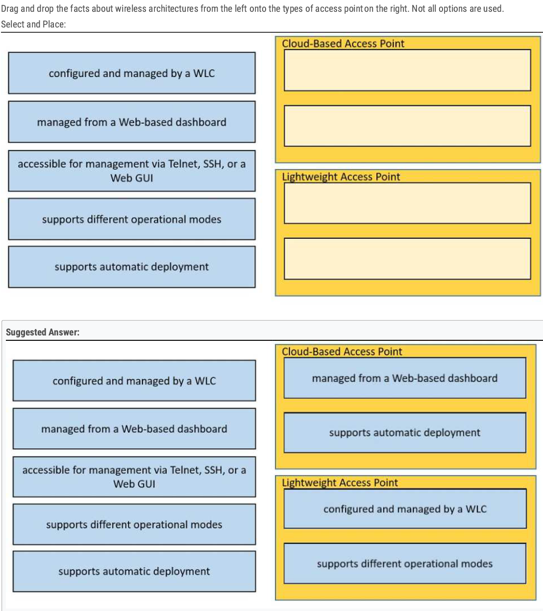
Lightweight AP supports different operational modes (Local Mode, Monitor Mode, Sniffer Mode)
B✅
B✅
TACACS+ — because it supports separate authentication and authorization.
B✅
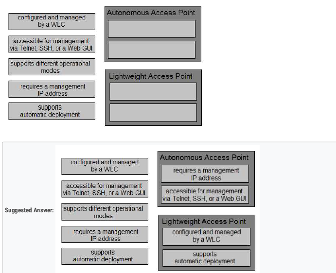
A✅
C D✅
C✅
LAG on WLC treats all ports as one logical port. D✅
- Access Points that use Power over Ethernet (PoE) need to “negotiate” how much power they can draw from the switch.
- This negotiation is done using Cisco Discovery Protocol (CDP) or LLDP (industry standard).
B✅
B C✅

C✅
When more than one AP-manager interface is configured, an AP will join the controller by selecting the least-loaded AP Manager.
C✅
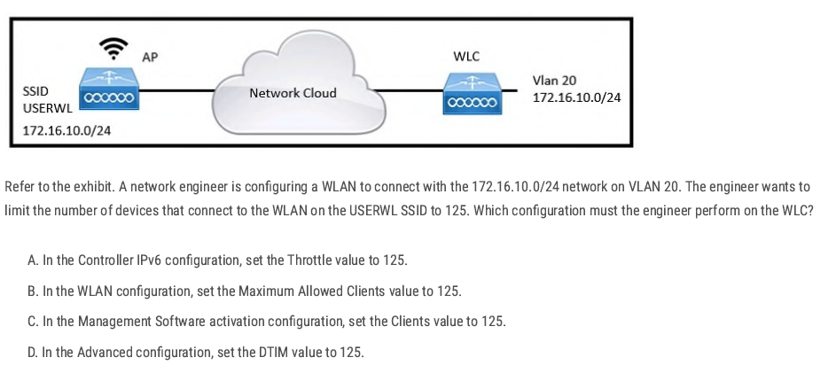
B✅
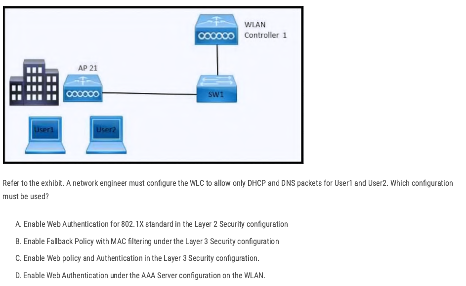
Layer 3 Web Authentication (web policy) allows only DHCP and DNS packets before the user authenticates. All other traffic is blocked until authentication succeeds.
C✅
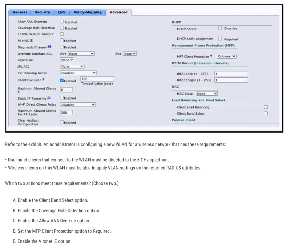
A C✅
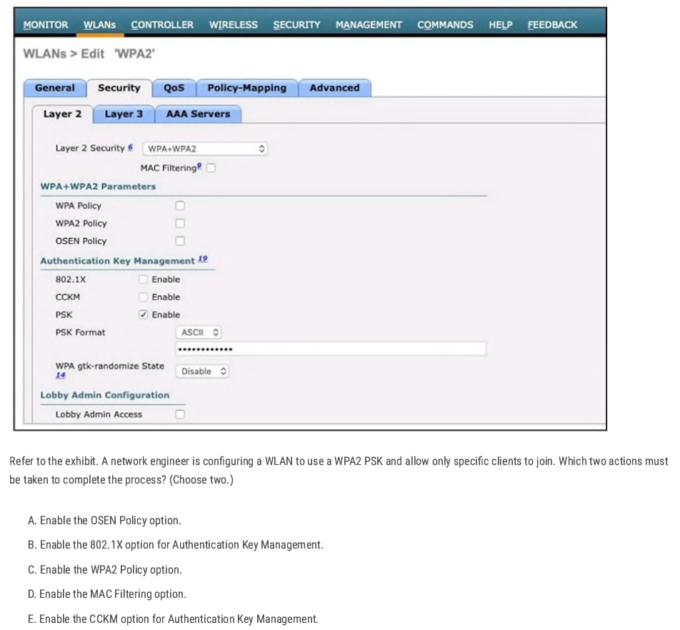
C B✅
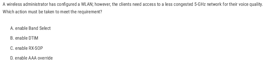
A✅
C✅
AP-manager = CAPWAP tunnel source.
C✅
B✅
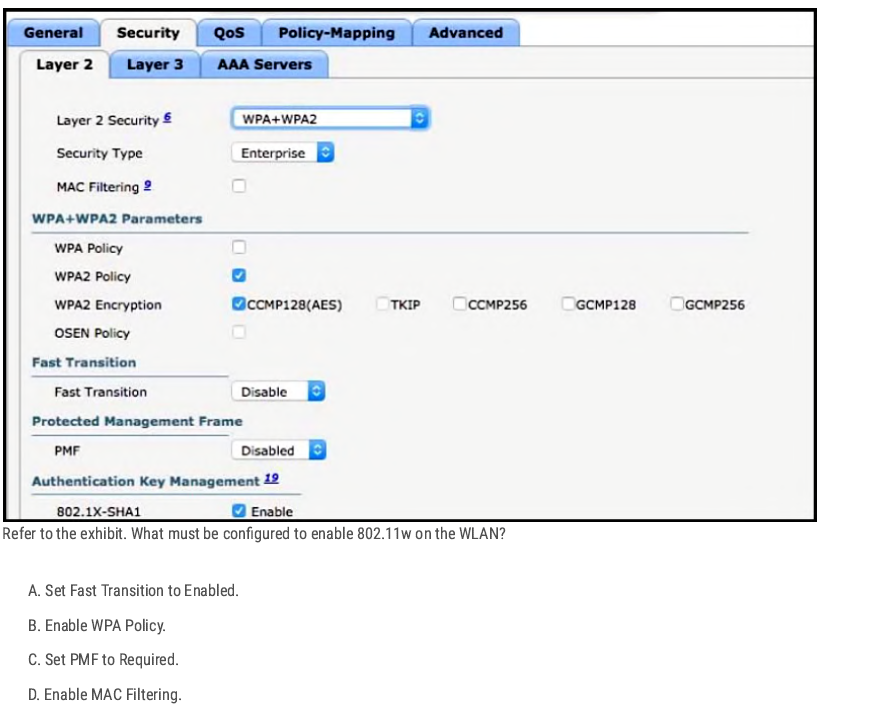
- 802.11w = Protected Management Frames (PMF).
- In the exhibit, you see PMF (Disabled).
C✅
C✅
CD✅
B✅
A✅
- Opportunistic Wireless Encryption (OWE) is defined in WPA3.
- It provides encryption without authentication.
- This means that even on an open Wi-Fi network (no password), traffic is still encrypted between the client and the AP.
B✅
D✅
A✅
C✅
- The goal is to minimize association (roaming) time as clients move between APs.
- 802.11k helps with this by letting the AP provide the client with a neighbor report (list of nearby APs on both 2.4 GHz and 5 GHz).
D✅
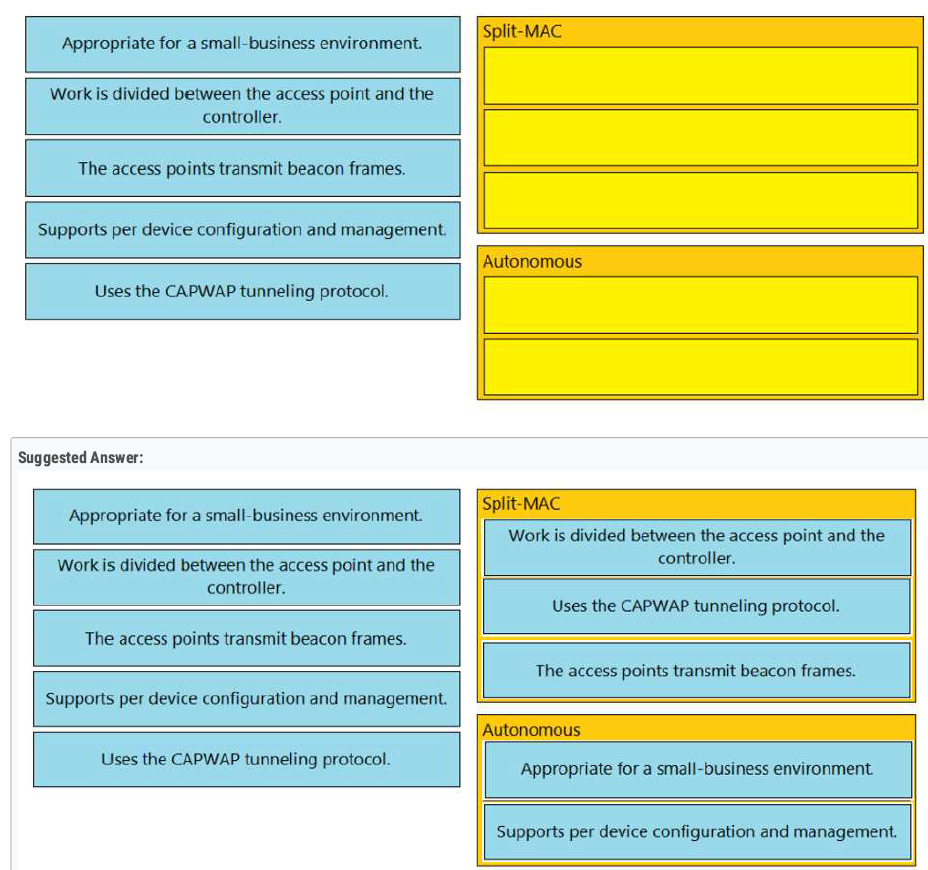
B E ✅
Load balancers → WLC handles balancing by itself.❌
When you add a new WLC, the two extra things you should set up are:
- Configure additional VLANs so that different SSIDs (such as guest, voice, and corporate) can be mapped to the correct networks.
- Configure additional security policies → to protect the WLAN (WPA2/WPA3, ACLs, RADIUS, etc.).
B E ✅
When setting up a new WLAN on a Cisco WLC, the basic workflow is:
- Authentication server (RADIUS/TACACS) configuration.
- Dynamic interface creation (maps SSIDs to VLANs).
- Create the WLAN (SSID) and bind it to the dynamic interface. 👉 This step connects the wireless side (SSID) to the wired side (VLAN).
D ✅
AB ✅
- 802.11a works in the 5 GHz band.
- Advantage: it provides more nonoverlapping channels (much more than 2.4 GHz’s 3 channels).
D✅
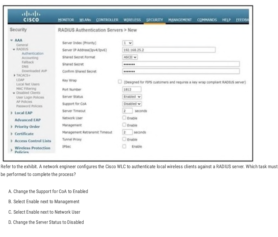
When configuring a RADIUS server on a Cisco WLC:
- Server Status = Enabled → Makes the RADIUS server active.
- To use the RADIUS server for wireless client authentication, you must check Network User (Enable).
- Without this, the WLC will not send wireless client authentication requests to the RADIUS server.
C✅
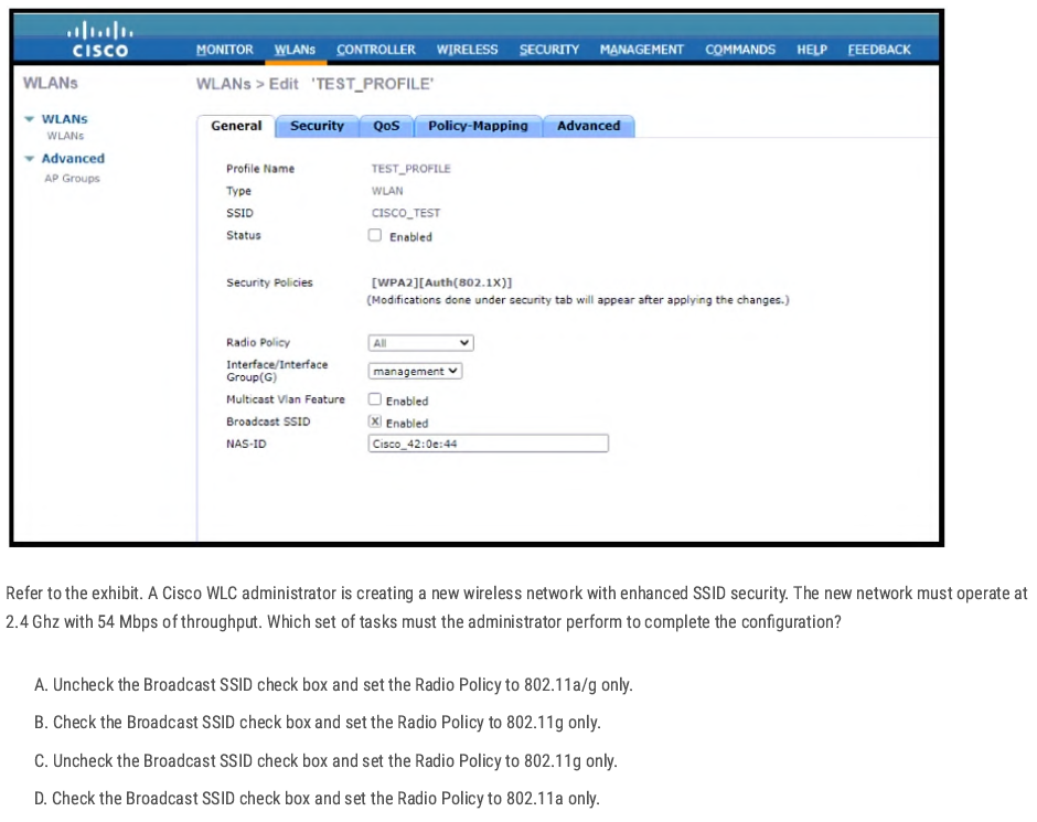
802.11g uses 2.4GHz and throughput up to 54 Mbit/s. “enhanced SSID security” = hiding the SSID, so we must uncheck the Broadcast SSID option
C✅
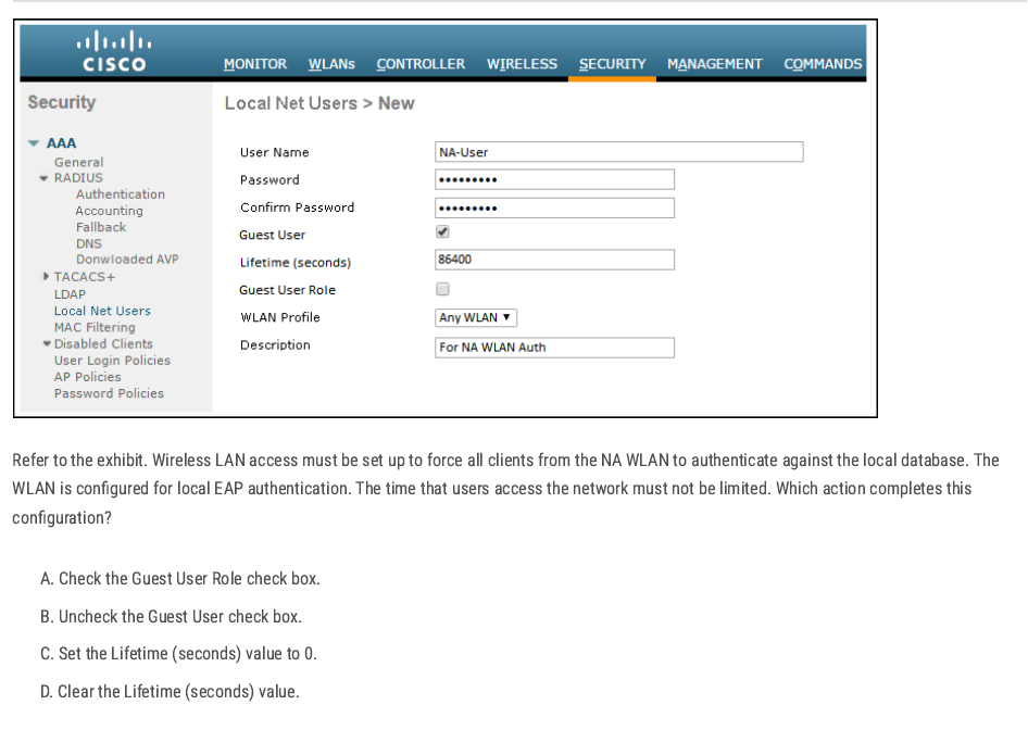
C✅
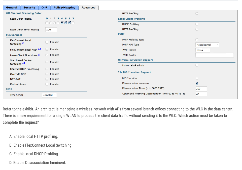
FlexConnect Local Switching — allows branch APs to handle data traffic locally instead of sending it back to the WLC.
B✅
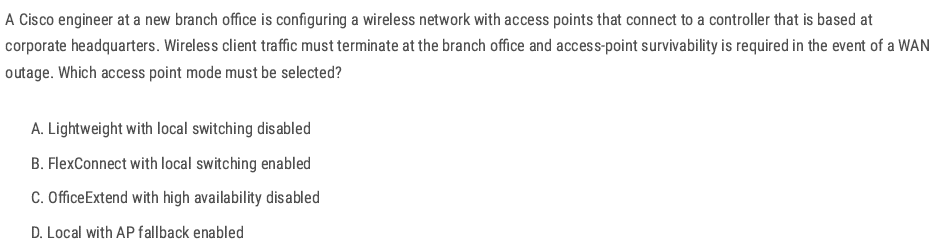
B✅
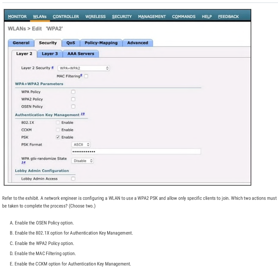
C D✅
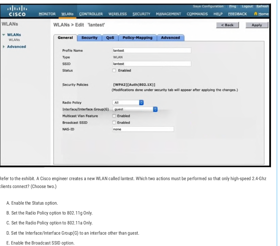
802.11g → Operates at 2.4 GHz
- By default, the WLAN is mapped to the guest interface (seen in the exhibit).
- To make this production-ready, you need to map the WLAN to another interface (e.g., a corporate VLAN instead of guest).
B D✅
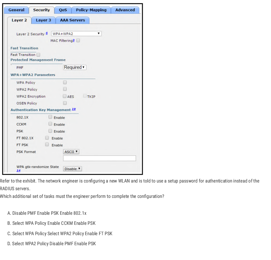
D✅

B D✅
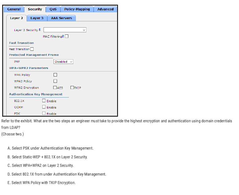
To get the highest security with domain credentials (LDAP):
- Use WPA2 (strongest encryption). ✅
- Use 802.1X (Enterprise authentication with usernames/passwords). ✅
C D✅
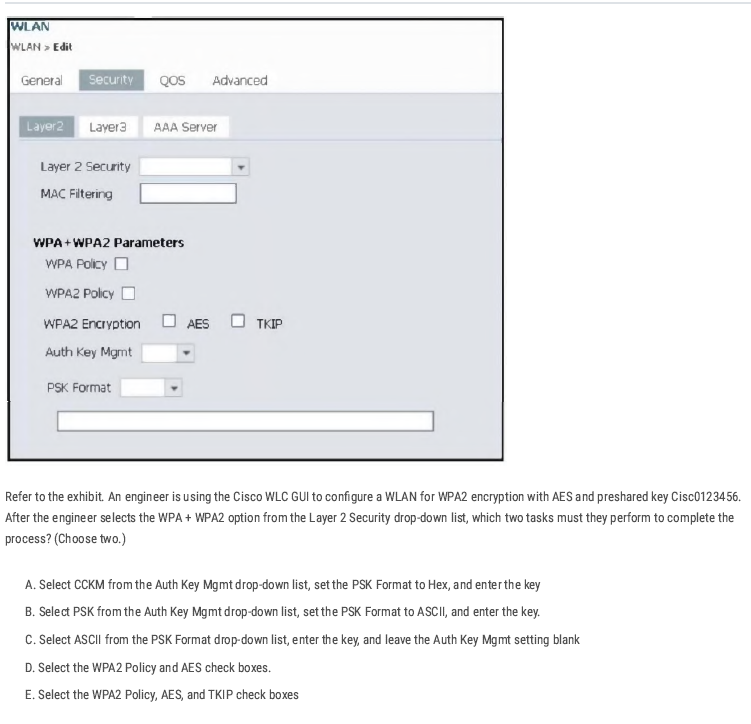
B D✅
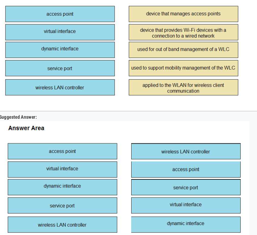
The fix: install a publicly trusted third-party certificate (e.g., DigiCert, GoDaddy, Let’s Encrypt) on Cisco ISE so both employees and contractors trust it automatically.
B ✅
To make SIP Call Admission Control work on WLC:
- Turn on Media Session Snooping → so the WLC can detect SIP calls.
- Set QoS to Platinum → highest priority for voice traffic.
C D ✅
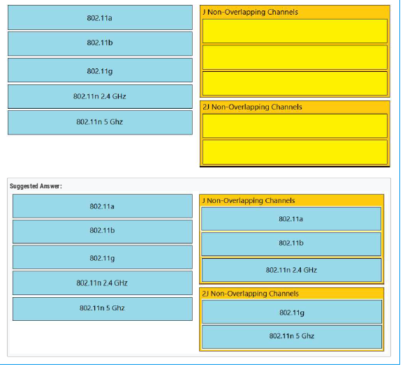
- Local mode = 2 CAPWAP tunnels (all traffic to WLC).
- FlexConnect = traffic can stay local (no tunnel for data).
A✅
- In local mode, an AP forms a CAPWAP tunnel (control + data) with the WLC.
- This tunnel runs over IP (UDP ports 5246 for control, 5247 for data).
- As long as the AP can reach the WLC’s management/AP-manager interface IP (through L2/L3 network), it doesn’t matter which switch it’s connected to.
D✅
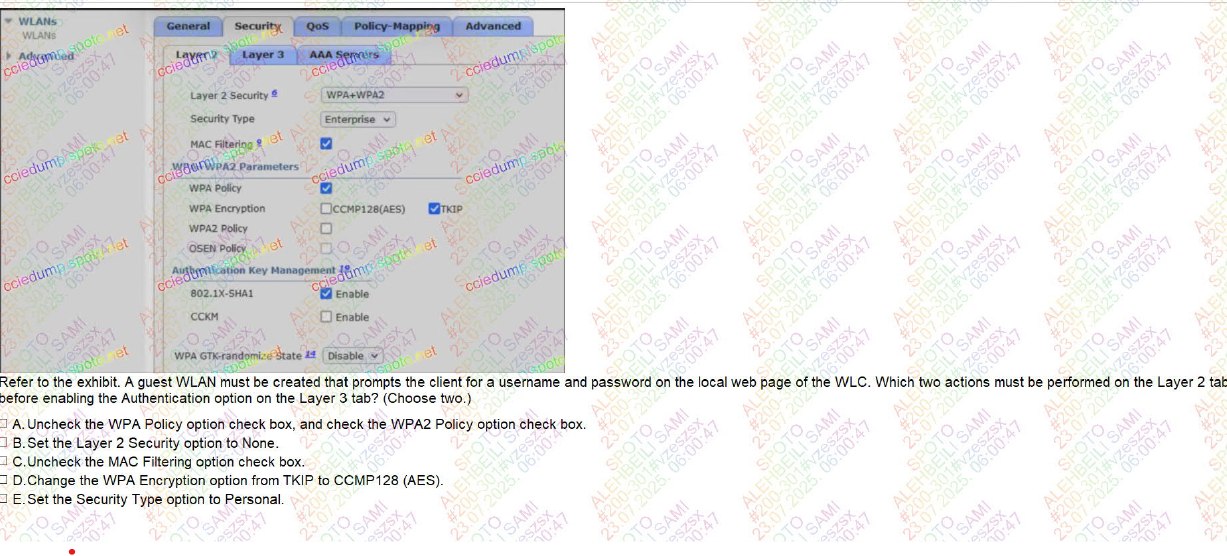
BC ✅
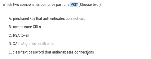
- A CA issues and manages certificates.
- A CRL is a list of revoked certificates.
BD ✅
CCNA Volume 2
Access Control List
What is an Access Control List
- An access list (ACL) is a set of rules for controlling traffic and reducing network attacks. ALCs filter traffic based on rules(IP address, protocol, or port) defined for incoming and outgoing traffic on the network.
Access Control List Feature
- Configuring an ACL in global config mode will not make the ACL take effect.
- The ACL must be applied to an interface.
- ACLs are applied either inbound or outbound.
- When the router checks a packet against the ACL, it processes the ACEs (Access Control Entries) in order, top to down in sequential order.
- If the packet matches one of the ACEs in the ACL, the router takes the action and stops processing the ACL. All entries below the matching entry will be ignored.
- The interface will take action based on the match condition. There are two possible actions: permit and deny.
- If the permit condition matches, a packet will be allowed to pass from the interface.
- If the deny condition matches, the packet will be destroyed immediately
- A maximum of one ACL can be applied to a single interface per direction. Inbound: Maximum one ACL Outbound: Maximum one ACL
- Every ACL has a default deny statement at the end of it.
- What will happen if a packet doesn’t match any of the entries in an ACL?
There is an ‘implicit deny’ (if source IP = any, then deny) at the end of all ACLs there’s an invisible rule. The implicit deny tells the router to deny all traffic that doesn’t match any of the configured entries in the ACL.
deny any
So if you forget to add a permit statement, all traffic gets blocked.
Type of Access Control List
- Standard Access List (Basic): Filter traffic based only on source IP address. By using numbers 1-99 or 1300-1999, the router will understand it as a standard ACL and the specified address as the source IP address. Typically applied close to the destination.
! Step 1: Define ACL
access-list <1-99> permit|deny <source> <wildcard>

! Step 2: Apply ACL to interface
interface <interface-id>
 ip access-group <1-99> in | out
- Extended Access List (Advanced): Filter traffic based on source and destination IP addresses, protocols, port numbers, and other criteria. These use ranges from 100-199 and 2000-2699. Typically applied close to the source.
access-list <number> permit|deny <protocol> <source> <src_wildcard> <destination> <dest_wildcard> [eq <port>]
Applying Access Control List
Inbound access list:
- Definition: Traffic entering the router through an interface before routing decisions are made.
- Think: "Packets coming into the door."
- If denied, the router drops the packet immediately—saves CPU and bandwidth.
- Use Case: Good for filtering unwanted traffic as close to the source as possible.
Outbound access list:
- Definition: Traffic leaving the router through an interface after routing decisions are made.
- Think: "Packets going out the door."
- The router first checks the routing table → then applies ACL rules on the outbound interface.
- Use Case: Useful when you want to control traffic leaving for a specific destination network.
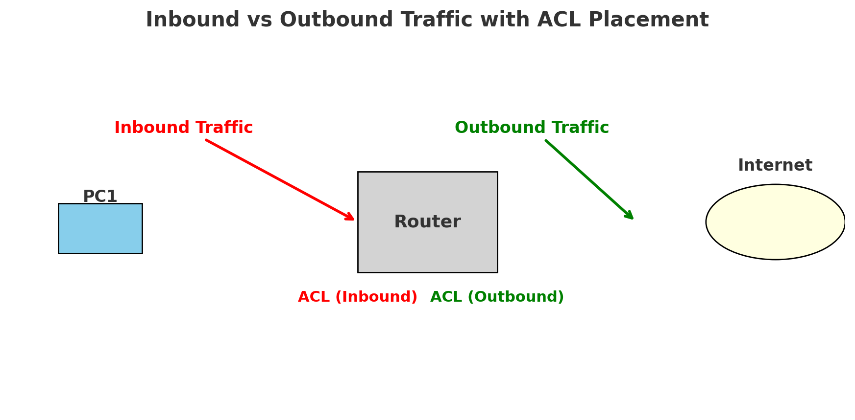
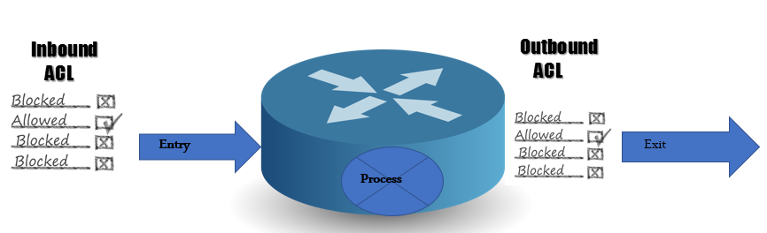
Applying the Access Control List
- Numbered access list: These are the access lists that cannot be deleted, specifically, one created. If we want to remove any rule from an access list, then this is not permitted in the case of a numbered access list. If we attempt to delete a rule from the access list, the entire access list will be deleted. The numbered access list can be used with both standard and extended access lists.
🔢 Numbered ACL vs 🏷️ Named ACL
1. Numbered ACL
- Uses numbers to identify the ACL.
- Example ranges:
- Standard ACL: 1–99 (expanded: 1300–1999)
- Extended ACL: 100–199 (expanded: 2000–2699)
- Editing: If you want to change one entry, you usually need to remove the entire ACL and re-create it.
- Usage: Simple, fast for small configs.
2. Named ACL
- Uses a name (instead of a number) to identify the ACL.
- Easier to read and understand (e.g.,
BLOCK-PC1instead of10). - Editing: You can enter ACL configuration mode and add/remove individual lines without deleting the whole ACL.
- Usage: Preferred in modern configs for flexibility and clarity.
no ip access-list {standard | extended} <NAME>
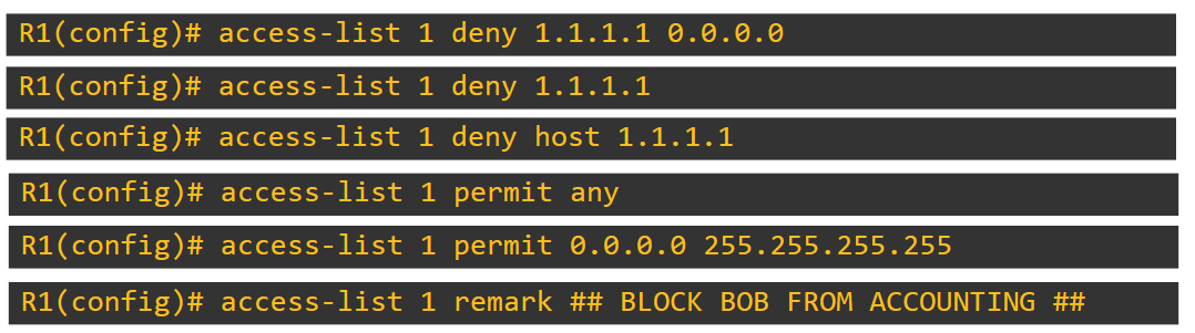
💡 We added 0.0.0.0 as a wildcard, which means only denying this IP address. If we add 0.0.0.255 as a wildcard, all IPs get denied.
Router(config-std-nacl)#deny 192.168.1.0 0.0.0.255 it means deny all the network completely
A remark in an access list is simply a comment or description you add to make the ACL more readable and understandable
- Named Access List: In this type of access list, a name is assigned to identify an access list. These can be used with both standards and extended access lists.
R1(config)# access-list standard [name ] MY_ACL
R1(config-std-nacl)# deny 192.168.1.0 0.0.0.255
R1(config-std-nacl)#permit any
R1(config)# int fa0/5
R1(config-if)# ip access-group MY_ACL out
How can the staff department be denied access to the server?
The administrator can fix this problem in two ways. He can apply an inboard ACL to the F0/0 interface, or he can apply an outbound ACL to the F0/2 interface
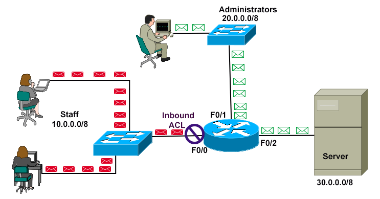
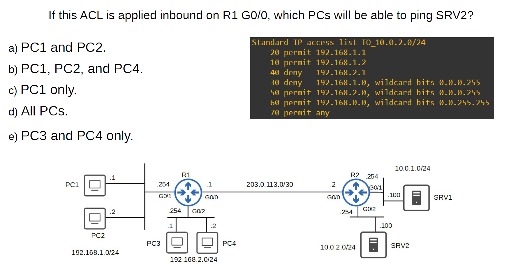
- D
How to delete a rule inside the access list?
- Numbered Access List
Router(config)#ip access-list extended 101
💡 This deletes all entries in access-list 100.
numbered ACLs, you have to delete the entire ACL and re-create it without the unwanted entries.
numbered ACLs, you have to delete the entire ACL and re-create it without the unwanted entries.
- Named Access List
Router#show access-lists
Extended IP access list 101
    20 deny tcp host 192.168.1.20 host 192.168.3.100 eq www (27 match(es))
    30 deny icmp host 192.168.1.10 host 192.168.3.100 (4 match(es))
    40 permit ip any any


Router(config)#ip access-list extended 101
Router(config-ext-nacl)#no 20 (sequence number) **or** no 30 deny icmp host 192.168.1.10 host 192.168.3.100
Extended Access List (Advanced)
In the standard Access List, we permit the device for everything, but with the Extended Access List, you can specify with service permit and with service deny
With Extended Access lists, you can evaluate additional packet information, such as:
- Source and destination IP address
- Type of TCP/IP Protocol(TCP, UDP, IP)
- source and destination port numbers.
Router(config)#access-list [number 100–199 | 2000–2699] [permit | deny] [protocol] [source IP] [wildcard] [destination IP] [wildcard] [operator] [port]
operator:
● eq 80 = equal to port 80 ● gt 80 = greater than 80 (81 and greater) ● lt 80 = less than 80 (79 and less) ● neq 80 = NOT 80 ● range 80 100 = from port 80 to port 100
Allow traffic from 10.0.0.0/16 to access the server at 2.2.2.2/32 using HTTPS (Numbered Access List)
Router(config)# access-list 110 permit tcp 10.0.0.0 0.0.255.255 2.2.2.2 0.0.0.0 eq 443
Hosts in 192.168.1.0/24 can’t use HTTPS to access SRV1. (Named Access List)
R1(config)#ip access-list extended HTTP_SRV1
R1(config-ext-nacl)#deny tcp 192.168.1.0 0.0.0.255 host 10.0.1.100 eq 443
R1(config-ext-nacl)#permit ip any any
R1(config-ext-nacl)#interface g0/1
R1(config-if)#ip access-group HTTP_SRV1 in
Extended ACLs
### ACL sequence numbers:
- Numbered ACLs → ❌ No sequence numbers. Rules are applied in the order you type them. To edit, you usually delete and rebuild.
- Named ACLs → ✅ Support sequence numbers (default: 10, 20, 30 …) sequence numbers (default
- You can insert a rule at a specific number.
- You can remove a rule using its number (
no 15). - You can re-sequence to clean up numbering (
ip access-list resequence NAME 10 10).
ip access-list standard BLOCK-PC
  10 deny host 192.168.1.10
  20 permit any
ip access-list standard BLOCK-PC
  15 deny host 192.168.1.20
Standard Access-List lab
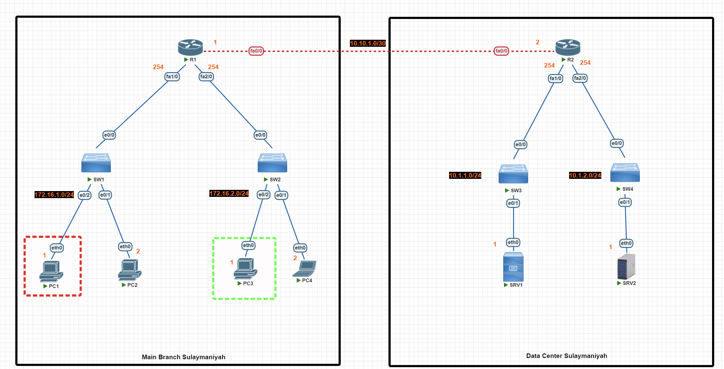
In this scenario, we are using standard access lists to perform the following network traffic control tasks:
- Block PC1 from accessing SRV1 (using a numbered standard access list).
- Allow only PC3 to access SRV2 (using a named standard access list).
Basic IP Configuration
End-User Devices
PC1>ip 172.16.1.1 255.255.255.0 172.16.1.254

PC2>  ip 172.16.1.2 255.255.255.0 172.16.1.254


PC3>ip 172.16.2.1 255.255.255.0  172.16.2.254

PC4> ip 172.16.2.2 255.255.255.0 172.16.2.254
Router(R1)
R1#conf t
R1(config)#int fa1/0
R1(config-if)#ip add 172.16.1.254 255.255.255.0
R1(config-if)#no shutdown
R1(config-if)#exit
R1(config)#int fa2/0
R1(config-if)#ip add 172.16.2.254 255.255.255.0
R1(config-if)#no shutdown
R1(config-if)#exit
R1(config)#int fa0/0
R1(config-if)#ip add 10.10.1.1 255.255.255.252
R1(config-if)#no shut
R1(config-if)#exit
R1(config)#exit
R1#wr
Router (R2)
R2#conf t
R2(config)#int fa0/0
R2(config-if)#ip add 10.10.1.2 255.255.255.252
R2(config-if)#no shut
R2(config)#int fa1/0
R2(config-if)#ip add 10.1.1.254  255.255.255.0
R2(config-if)#no shut
R2(config-if)#exit
R2(config)#int fa2/0
R2(config-if)#ip add 10.1.2.254 255.255.255.0
R2(config-if)#no shut
R2(config-if)#exit
R2(config)#exit
R2#wr
Server
SRV1> ip 10.1.1.1 255.255.255.0 10.1.1.254


SRV2> ip 10.1.2.1 255.255.255.0  10.1.2.254
OSPF Configuration
Router R1
R1#conf t
R1(config)#
R1(config)#router ospf 1
R1(config-router)#network 10.10.1.0 0.0.0.3 area 0
R1(config-router)#network 172.16.1.0 0.0.0.255 area 0
R1(config-router)#network 172.16.2.0 0.0.0.255 area 0
R1(config-router)#passive-interface fa1/0
R1(config-router)#passive-interface fa2/0
R1(config-router)#exit
R1(config)#exit
R1#wr
Router R2
R2#conf t
R2(config)#
R2(config)#router ospf 1
R2(config-router)#network 10.10.1.0 0.0.0.3 area 0
R2(config-router)#network 10.1.1.0  0.0.0.255 area 0
R2(config-router)#network 10.1.2.0  0.0.0.255 area 0
R2(config-router)#passive-interface fa1/0
R2(config-router)#passive-interface fa2/0
R2(config-router)#exit
R2(config)#exit
R2#wr
Access List Configuration
💡 Standard Access List uses the source IP address. It is highly recommended that it be applied to the router near the destination if the destination is under your control.
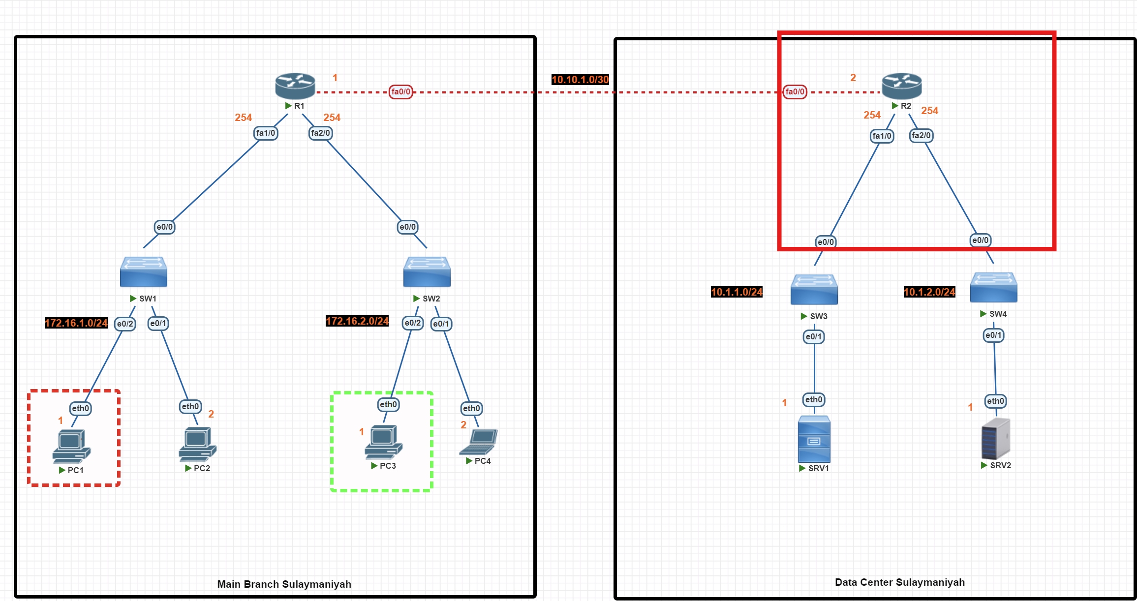
R2#conf t
R2(config)# access-list 1 deny 172.16.1.1
**R2(config)# access-list 1 permit any**
R2(config)#int fa1/0
R2(config-if)#ip access-group 1 out
R2(config-if)#exit

R2(config)#ip access-list standard allow_SRV1
R2(config-std-nacl)#permit 172.16.2.1
R2(config-std-nacl)#exit
R2(config)#int fa2/0
R2(config-if)#ip access-group allow_SRV1  out
R2(config-if)#exit
R2(config)#exit
R2#wr
Important: The permit any rule is essential
By default, the access list ends with a hidden 'deny any role' entry. We use the command below to permit other devices.
**R2(config)# access-list 1 permit any**
Access List verification
R2#show access-list
This command is useful for verifying whether your access lists are working properly. It shows you how many packets matched each rule in your configuration.
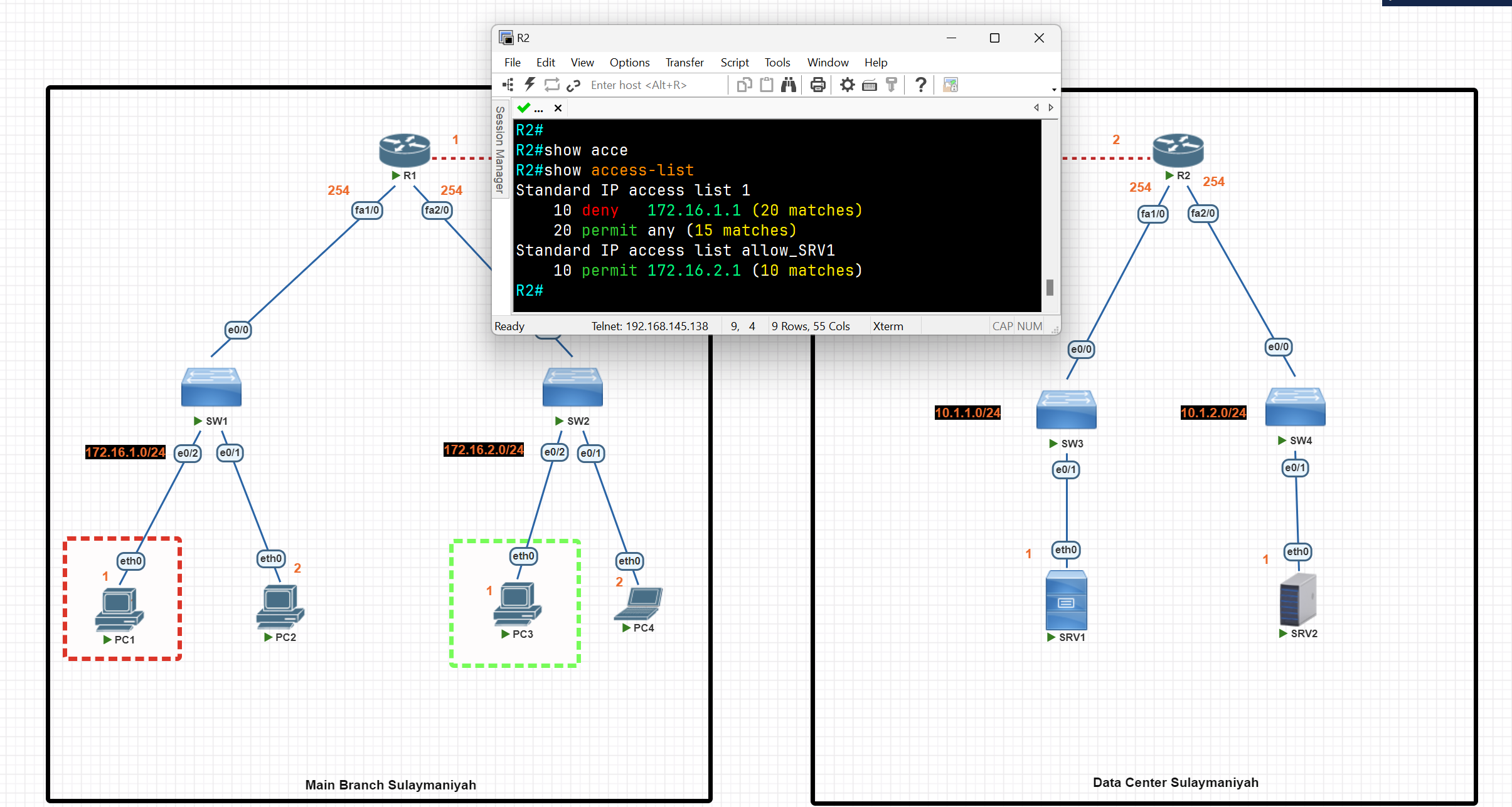
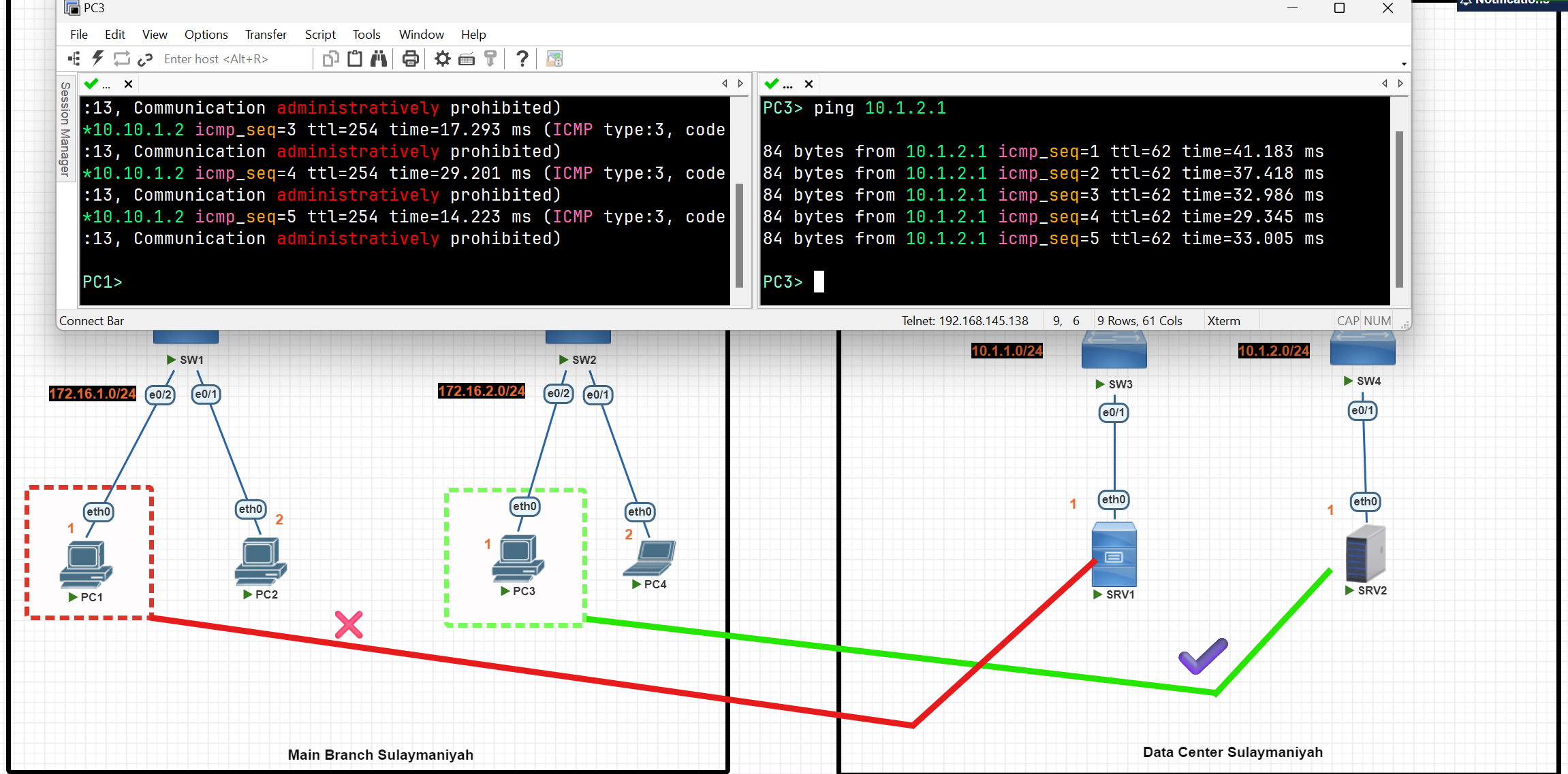
Extended Acess-List
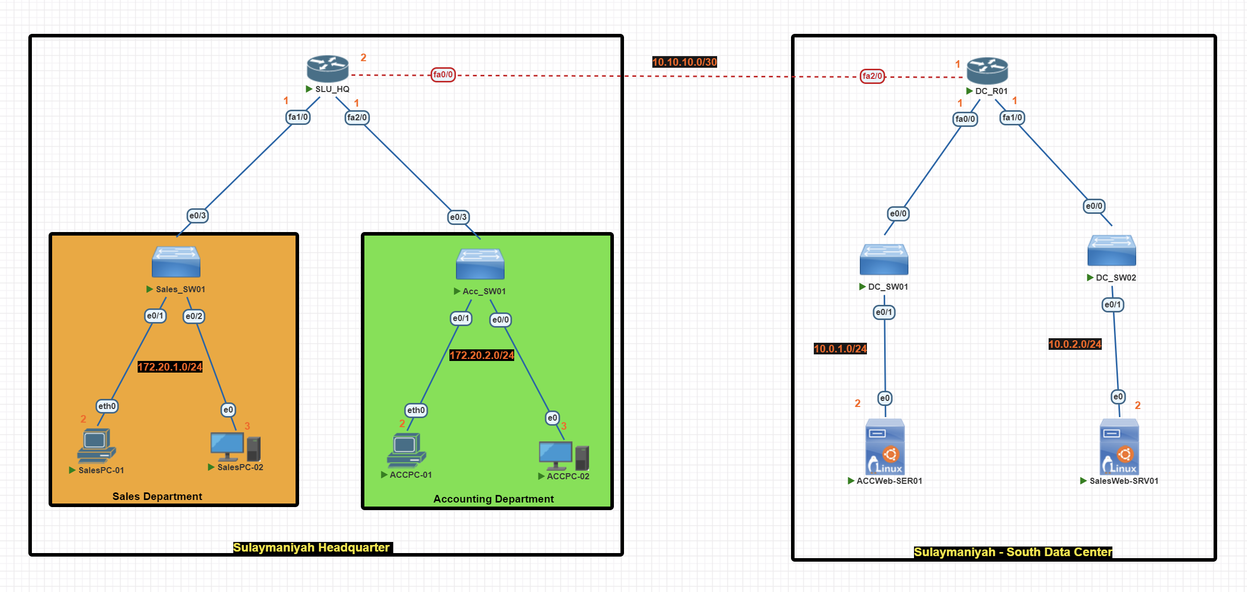
In this scenario, we are using extended access lists to perform the following network traffic control tasks:
- Block Sales Department from accessing ACCWeb-SER01 (using a numbered extended access list).
- Block Accounting Department from accessing SalesWeb-SER01 (using a named standard access list).
- Accounting PCs couldn’t access Sales PCs.
Basic IP Configuration
End-User Devices
SalesPC-01> ip 172.20.1.2 255.255.255.0 172.20.1.1


SalesPC-02> ip 172.20.1.3 255.255.255.0 172.20.1.1
ACCPC-01> ip 172.20.2.2 255.255.255.0 172.20.2.1
ACCPC-01> ip 172.20.2.3 255.255.255.0 172.20.2.1
Router(SLU_HQ)
SLU_HQ#conf t
SLU_HQ(config)#
SLU_HQ(config)#int fa1/0
SLU_HQ(config-if)#ip add 172.20.1.1 255.255.255.0
SLU_HQ(config-if)#no shut
SLU_HQ(config-if)#exit
SLU_HQ(config)#int fa0/0
SLU_HQ(config-if)#ip add 10.10.10.2 255.255.255.252
SLU_HQ(config-if)#no shut
SLU_HQ(config-if)#exit
SLU_HQ(config)#int fa2/0
SLU_HQ(config-if)#ip add 172.20.2.1 255.255.255.0
SLU_HQ(config-if)#no shut
SLU_HQ(config-if)#exit
SLU_HQ(config)#exit
SLU_HQ#wr
Router (DC_R01)
DC_R01#conf t
DC_R01(config)#int fa2/0
DC_R01(config-if)#ip add 10.10.10.1 255.255.255.0
DC_R01(config-if)#no shut
DC_R01(config-if)#exit

DC_R01(config)#int fa0/0
DC_R01(config-if)#ip add 10.0.1.1 255.255.255.0
DC_R01(config-if)#no shut
DC_R01(config-if)#exit

DC_R01(config)#int fa1/0
DC_R01(config-if)#ip add 10.0.2.1 255.255.255.0
DC_R01(config-if)#no shut
DC_R01(config-if)#exit
DC_R01(config)#exit
DC_R01#wr
RIP Configuration
Router(SLU_HQ)
DC_R01#conf t
DC_R01(config)#router rip
DC_R01(config-router)#network 10.10.10.0
DC_R01(config-router)#network 10.0.1.0
DC_R01(config-router)#network 10.0.2.0
DC_R01(config-router)#no auto-summary
DC_R01(config-router)#version 2
DC_R01(config-router)#passive-interface fa0/0
DC_R01(config-router)#passive-interface fa1/0
DC_R01(config-router)#exit
DC_R01(config)#exit
DC_R01#wr
Router (DC_R01)
SLU_HQ#conf t
SLU_HQ(config)#
SLU_HQ(config)#router rip
SLU_HQ(config-router)#network 10.10.10.0
SLU_HQ(config-router)#network 172.20.1.0
SLU_HQ(config-router)#network 172.20.2.0
SLU_HQ(config-router)#no auto-summary
SLU_HQ(config-router)#version 2
SLU_HQ(config-router)#passive-interface fa1/0
SLU_HQ(config-router)#passive-interface fa2/0
SLU_HQ(config-router)#exit
SLU_HQ(config)#exit
SLU_HQ#wr
Access List Configuration
💡 Extended Access List is highly recommended to be applied to the router nearest the source.
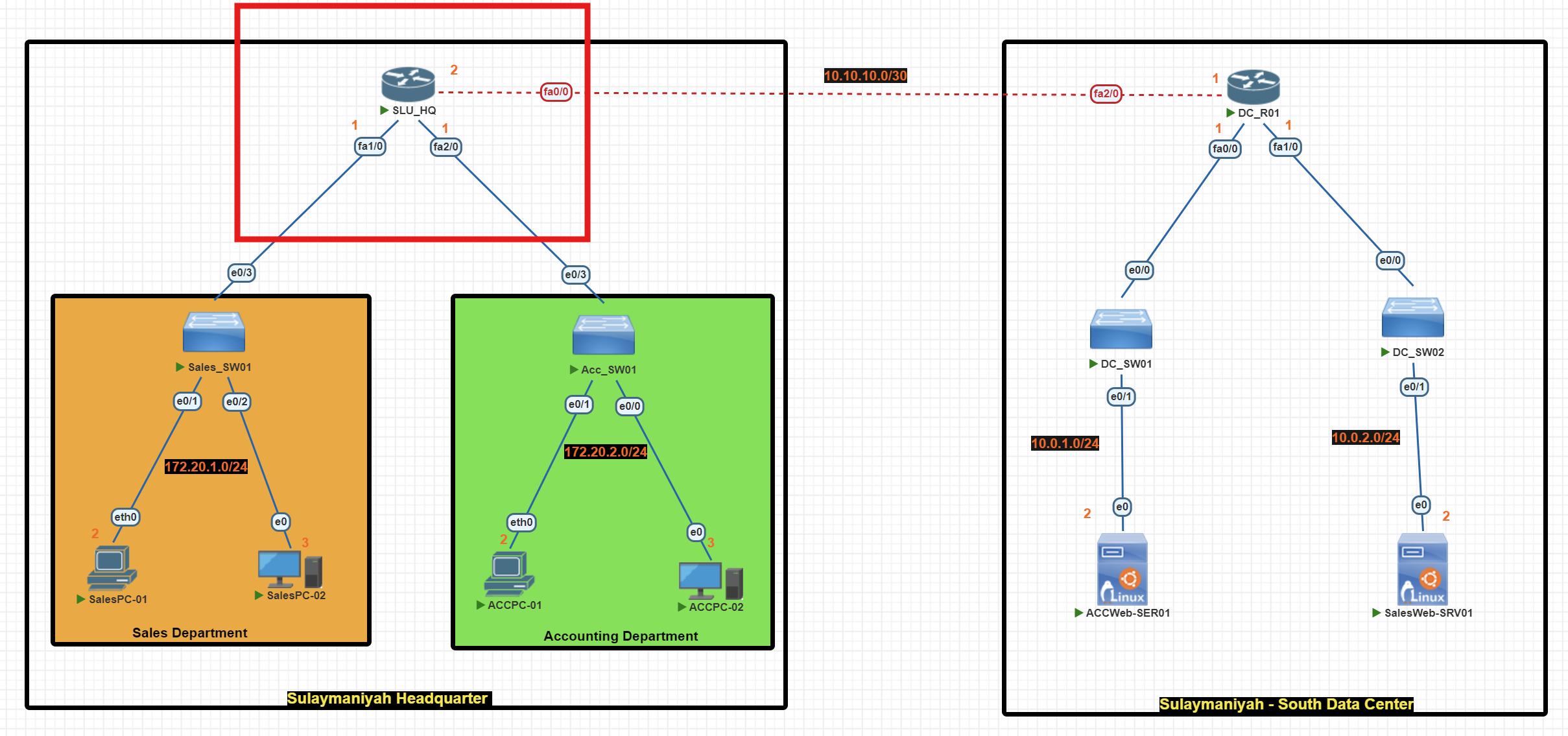
SLU_HQ(config)#access-list 101 deny tcp 172.20.1.0 0.0.0.255 host 10.0.1.2 eq 80

SLU_HQ(config)#access-list 101 deny ip 172.20.1.0 0.0.0.255 172.20.2.0 0.0.0.255

SLU_HQ(config)#access-list 101 **permit ip any any**

SLU_HQ(config)#int fa 1/0
SLU_HQ(config-if)#ip access-group 101 in

SLU_HQ(config-if)#exit
SLU_HQ(config)#exit
SLU_HQ#wr
SLU_HQ(config)#ip access-list extended  Acc_Rules
SLU_HQ(config-ext-nacl)#deny tcp 172.20.2.0 0.0.0.255 host 10.0.2.2 eq 80
SLU_HQ(config-ext-nacl)#deny ip 172.20.2.0 0.0.0.255 172.20.1.0 0.0.0.255
SLU_HQ(config-ext-nacl)#**permit ip any any**
SLU_HQ(config-ext-nacl)#exit
SLU_HQ(config)#int fa2/0
SLU_HQ(config-if)#ip access-group Acc_Rules in
SLU_HQ(config-if)#exit
SLU_HQ(config)#exit
SLU_HQ#wr
💡 By default, the access list ends with an implicit
deny any. We use the commandpermit ip any anyto allow traffic from all other devices.
Access List verification
R2#show access-list
This command is very useful for verifying if your access lists are working and tells you how many packets matched each rule.
Before applying the extended access list
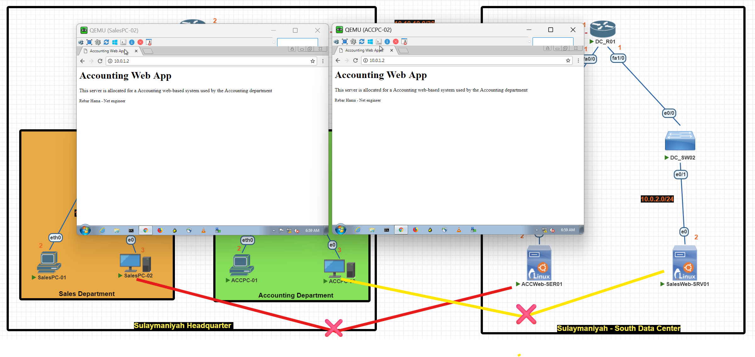
After applying the extended access list
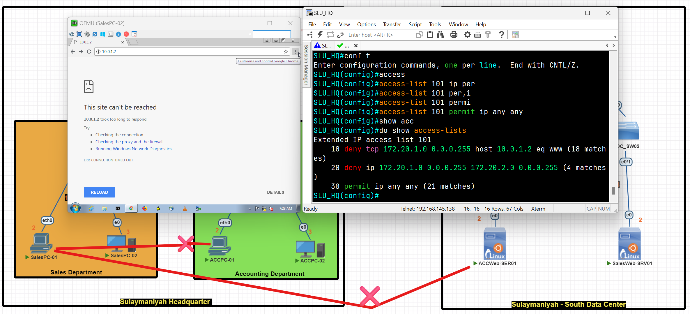
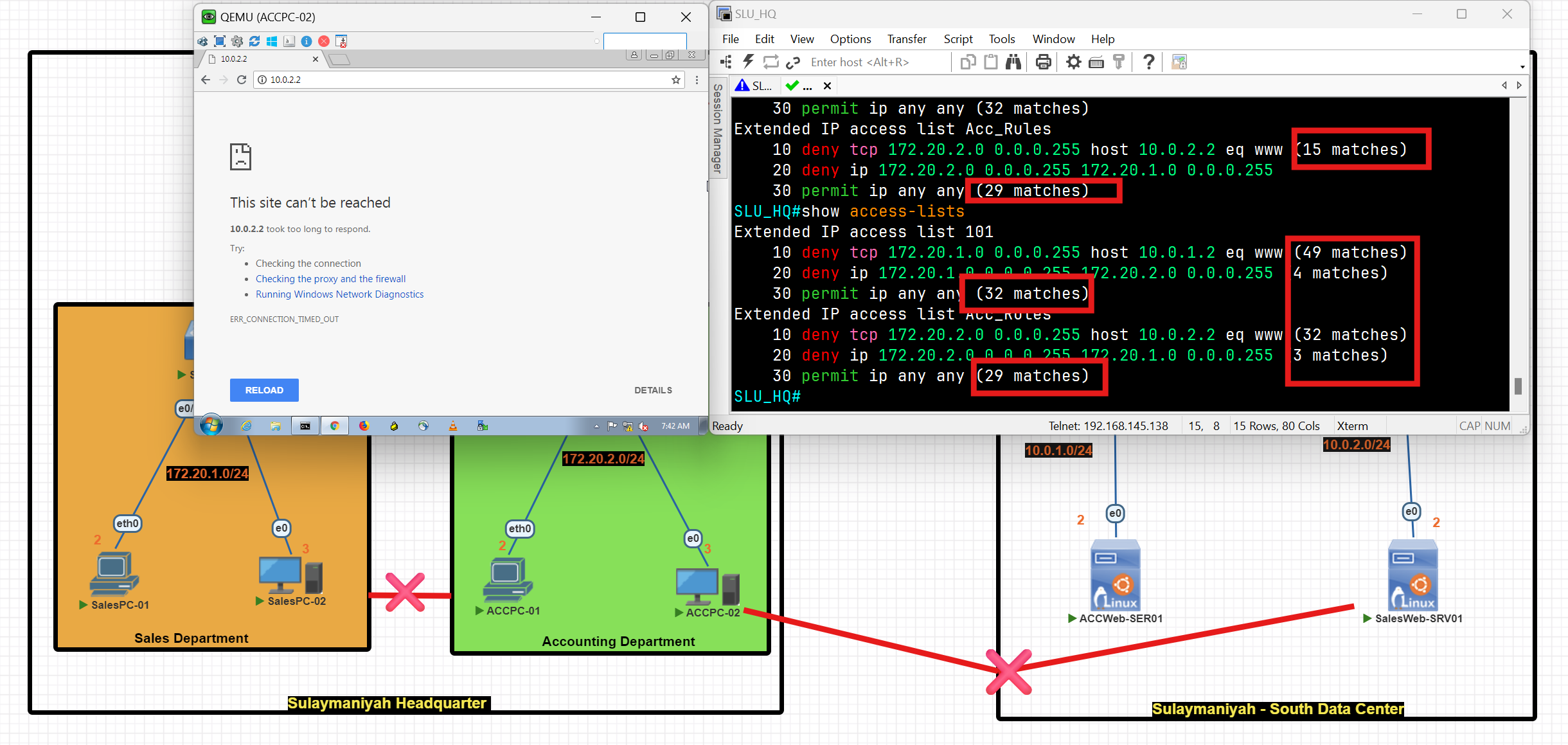
Access List Questions
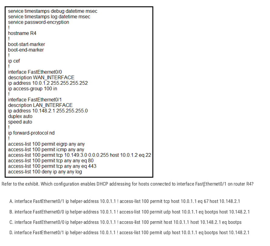
FastEthernet0/1 = LAN interface, DHCP uses UDP Between A and D
D✅
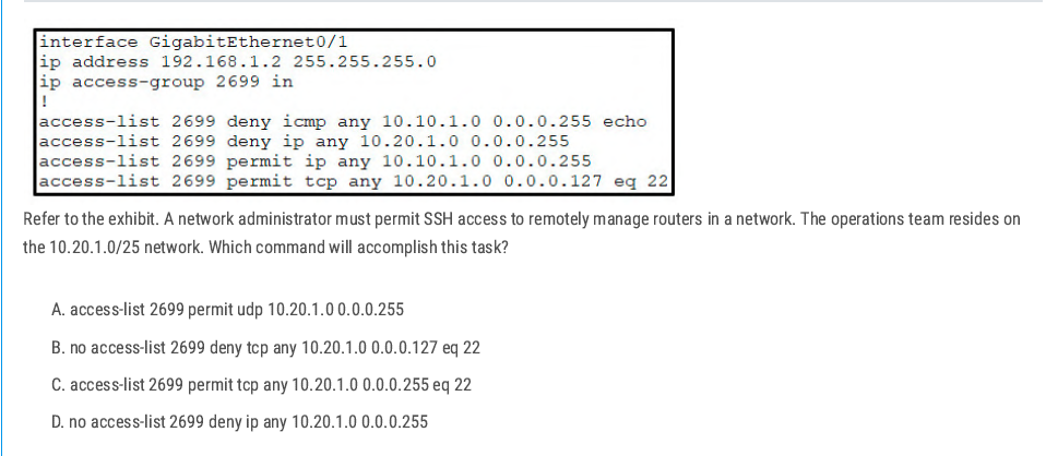
- The ACL has a line:
deny ip any 10.20.1.0 0.0.0.255 - That line blocks all traffic to the entire 10.20.1.0/24 network.
- SSH permit (
permit tcp any 10.20.1.0 0.0.0.127 eq 22) is written after it, but ACLs work top-down
D✅
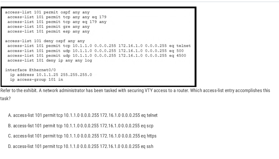
D✅
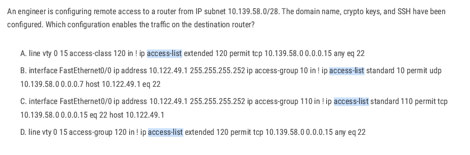
between A and D:
To restrict VTY (remote CLI) access, you must use access-class under the VTY lines, not access-group (that’s for interfaces).
A✅
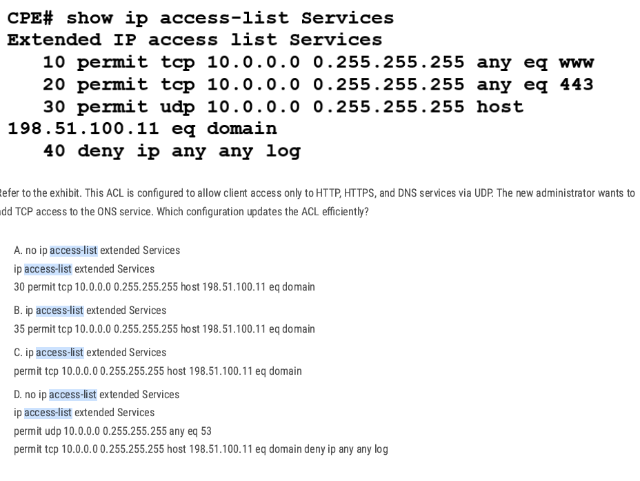
Best way: add one line to the ACL with a sequence number for efficiency.sequence number for efficiency
B✅
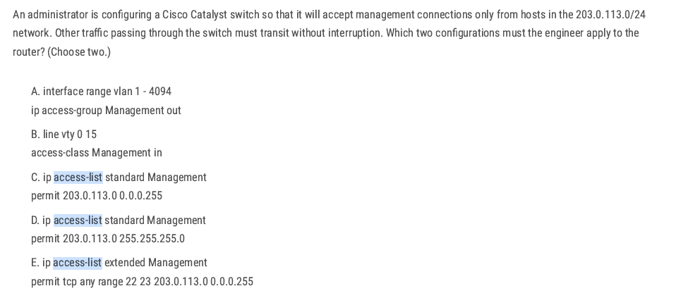
CB ✅
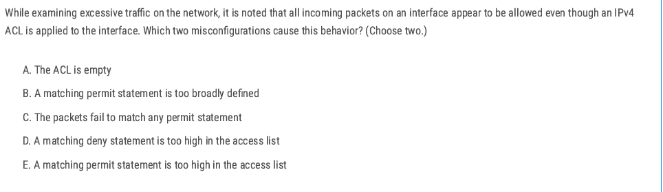
B E ✅
B. A matching permit statement is too broadly defined ✅
- Example:
permit ip any any. - This will match all packets immediately and allow everything.
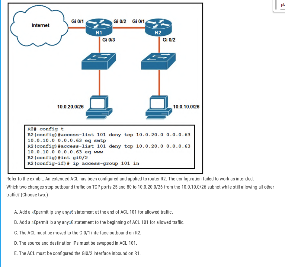
Add permit ip any any at the end – without a final permit, the implicit deny would block all other traffic. This line allows everything else after the specific denies.
Swap source and destination in ACL 101 – the denies are written with source = 10.0.20.0/26 and destination = 10.0.10.0/26, but we need to block traffic from 10.0.10.0/26 to 10.0.20.0/26 on ports 25 and 80. So the addresses must be reversed.
AD ✅
Securing Cisco Devices
Security Planes
Management Plane: The management plane is used to access, configure, manage, and monitor a network device. (This phase is about securing network devices)
Control Plane: The Control Plane consists of the protocols and processes that communicate between network devices in order to move data from source to destination. This includes routing protocols such as BGP, OSPF, and signaling protocols. (Responsible for building and maintaining the routing and switching tables.) In this phase, you can control which devices are allowed to receive OSPF updates.
Data plane: The data plane is responsible for transferring data from the source to the destination**.** This is where most data packets flow within the network device. (This phase is about securing user data moved across a network.)
D✅
Data plane function (switch tagging/untagging VLANs)
Data plane (switch forwarding decision). CD✅
A✅
Control plane → Handles routing protocols, builds routing tables, and makes forwarding decisions. D✅
AAA Servers
- AAA Server is a server that provides three important functions for network security: Authentication, Authorization, and Accounting (AAA). You can easily change/enable/disable account passwords, enforce strong password policies, and monitor account usage and user access.
Authentication: This is a process of verifying the identity of a user or a device attempting to access network resources.
Authorization: This is the process of determining what resources and services a user or device is allowed to access after authentication.
Accounting: This is the process of tracking user activity on a network.
The benefit of using an AAA server
Improve Security: By centralizing authentication and authorization, an AAA server can help to improve the security of a network by reducing the risk of unauthorized access.
Increased Scalability: AAA servers can be scaled to support large networks.
Reduced Administrative overhead: AAA Server can help to reduce administrative overhead by automating the process of authenticating and authorizing users.
aaa new-model is the master command that turns on AAA (Authentication, Authorization, and Accounting) on a Cisco device.
A✅
AAA External Server
- Radius Server
- LDAP Server
- Active-Directory Server
- TACACS+ Server
- Cisco Secure Access Control Server (ACS)
- Microsoft Active Directory
- Juniper Networks Contrail Access Control
- F5 BIG-IP Access Policy Manager (APM)
- Aruba ClearPass Policy Manager
| Feature | TACACS+ | RADIUS |
| Developed by | Cisco | Livingston Enterprises |
| Supports | Authentication and authorization | Authentication only |
| Transport protocol | TCP | UDP |
| Packet encryption | All packets are encrypted | Only the password is encrypted |
| Command authorization | Supported | Not supported |
Apply TACACS+
AAA Server LAB
In this scenario, we will create an AAA server and generate a username and password. After preparing the AAA server, we will apply the AAA configuration to the router. Consequently, when a device attempts to access the router, it should be authorized by requiring the entry of a username and password.
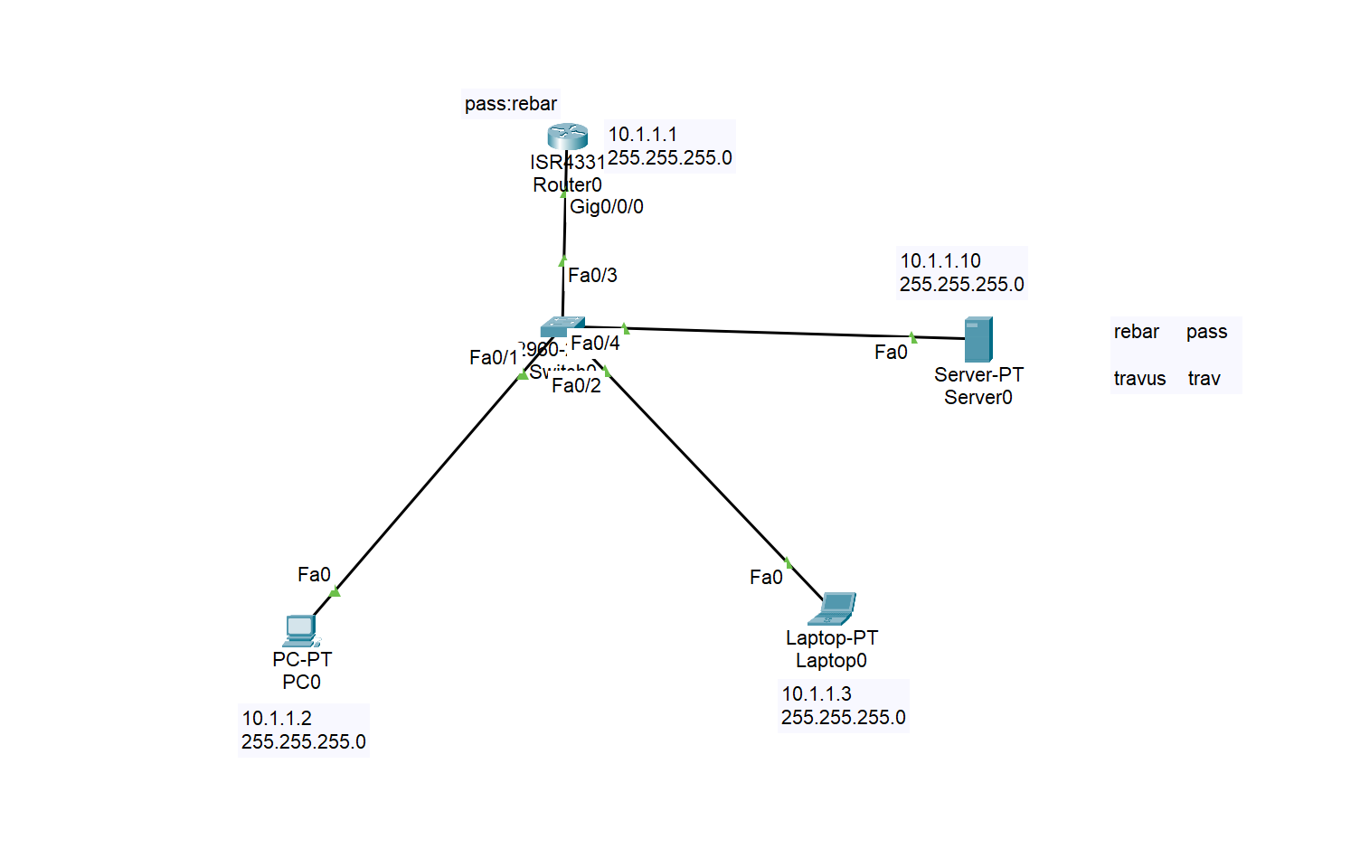
Configuring AAA Service on the server
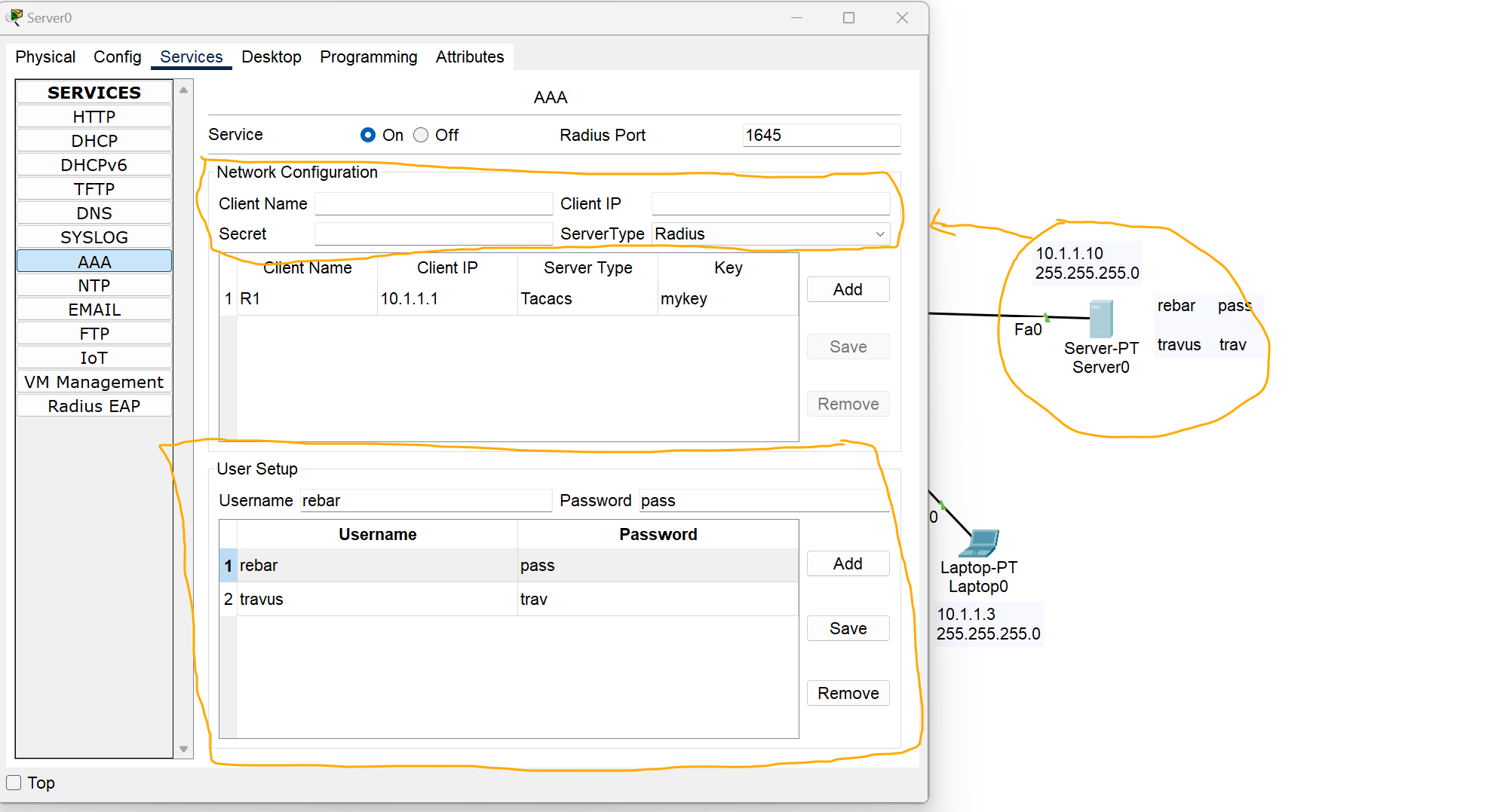
Network Configuration Section
Client Name: Name of the device to which you want to apply AAA rules.
Client IP: the IP address of the client, in this case, I added the IP address of the router.
Server Type: Select which type of server you need.
User Setup
Add your username and password as required.
Configuring TACACS+ AAA Server on A router
Router# Config terminal
Router(config)# enable secret (your password)  //create first password
Router(config)#aaa new-model  //enable the aaa service
Router(config)# aaa authentication login myauth[your name] group tacacs+ enable
Router(config)# tacacs-server host 10.1.1.10(server IP) key mykey (key generated at the server side)

Router(config)# line vty 0 4
Router(config)#login authentication myauth[your name] //Apple AAA authentication to VTY lines(Telnet,SSh etc)
Router(config)#exit

Router(config)# line vty 0   /// by using this command you can apply AAA configuration to console port
Router(config-line)# login authentication default
**R1#show aaa sessions**
As you can see, we have access to the router from two different users on two different devices.
Configuring Radius AAA Server on A router
We have the same scenario with the same approach, but some of the commands have changed
Router# Config terminal
Router(config)# enable secret (your password)  //create first password
Router(config)#aaa new-model  //enable the aaa service
Router(config)# aaa authentication login myauth[your name] group **radius** enable
**Router(config)# radius server  iserver(yourname)(key generated at the server side)
R1(config-radius-server)#address ipv4  host 10.1.1.10(server IP)
R1(config-radius-server)#key  mykey (key generated at the server side)**
Router(config)# line vty 0 4
Router(config-line)#login authentication myauth[your name] //Apple AAA authentication to VTY lines(Telnet,SSh etc)
Router(config)#exit

Router(config)# line vty 0   /// by using this command you can apply AAA configuration to console port
Router(config-line)# login authentication default
Use Local Accounts
- If you can’t install and use an external AAA server as discussed in the previous section, at a bare minimum, create separate local accounts for anyone who will give access to your device
Router# config terminal

Router(config)# username admin(write your user) secret admin122 (write your password)
to encrypt the password with a very secure algorithm, SHA1
Switch(config)#username rebar algorithm-type sha256 secret cisco
💡 If line vty 0 4 is configured for the AAA server, we should change the configuration
Router(config-line)#login authentication myauth[your name]

to

Router(config-line)#login local
Maximum Failed Attempts
- To avoid brute-force password attacks on the devices, you can configure a maximum number of failed login attempts so that a user will be locked out after their threshold.
Router# config terminal
Router(config)#login block-for <block-time-period> attempts <fail-attempts> within <login-attempt-time-period>
: Time to block login (sec)
: number of login attempts
<login-attempt-time-period: Time to watch for login Attempt
Example: If a login 3 times in 60 seconds, the user will be prevented from logging in for 120 seconds.
Router(config)#login block-for 120 attempts 3 within 60
This feature is applied to the local account.pkt
IP Service - Device Management
NTP(Network Time Protocol) Server
Internal System Clock: It is a software-based clock that relies on the device’s CPU and internal timer to keep track of time.
- The system clock retains the current time only while the device is powered on, once the router reboots, it resets.
- If the router doesn’t have a backup hardware clock, it may default to reference time(00:00 on January 1, 1970) after rebooting.
A synchronized clock is crucial for a network device for several reasons:
- Logging and Troubleshooting: Network devices generate log messages (Syslog) for events such as configuration changes, errors, and network incidents. Accurate timestamps are essential to understand the order and timing of these events.
- Security(Authentication and Encryption): Security protocols, such as IPsec and SSL/TLS, rely on synchronized clocks to function correctly.
- Compliance: Many industries have regulatory requirements( Such as PCI DSS) that mandate accurate timekeeping for logging and auditing.
- Time-Based Access Lists: Some devices may be configured with time-based access list or firewall rules that allow or deny traffic based on the time of the day.
- Network Automation: Some devices rely on the clock for scheduling tasks like backups. configuration updates.
Time configuration
Software Clock: the clock the router uses to timestamp logs, routing updates, and other software events. Stored in RAM and managed by the operating system.
clock set command is used to update software clock.
clock read calendar command is used to update software clock from hardware clock.
show clock command is used to view the current time of the device.
show clock detail command is used to view the device's current time with the time source.
C7200#clock set HH:MM:SS MONTH DAY YEAR
C7200#clock set 10:45:30 17 Apr 2024

C7200#show clock detail
10:45:51.871 UTC Wed Apr 17 2024
Time source is **user configuration**

C7200#clock read-calendar
C7200#show clock detail
09:20:51.783 UTC Thu Apr 17 2025
Time source is hardware calendar
Hardware Clock: A battery-powered clock that runs independently of the router’s OS. Inside the hardware(Real Time clock Chip).
calendar set command is used to update the hardware clock.
C7200#calendar set 14:35:00 27 Dec 2020

C7200#show calendar
14:35:07 UTC Sun Dec 27 2020
clock update-calendar command is used to update hardware clock from software clock.
💡
calendar setclock update-calendararen't working on emulators like GNS3, EVE-Ng.
Updating Time zone
Router(config)# clock timezone <ZONE_NAME> <UTC_OFFSET>
<ZONE_NAME>– Just a label you define (e.g.,IRAQ,Baghdad, or anything).<UTC_OFFSET>– Offset in hours from UTC. Use positive numbers for time ahead of UTC (like Iraq), and negative for behind.
C7200(config)#clock timezone Iraq 3
NTP (Network Time Protocol)
Network Time Protocol is an application layer protocol for time synchronization between TCP/IP network hosts.
- NTP clients request the time from NTP servers.
- A device can be an NTP Server and an NTP client at the same time.
- NTP uses UDP port 123 to communicate.
- Cisco devices can operate in three NTP modes: Server mode, Client mode, and Symmetric mode(Devices can also ‘peer’ with devices at the same stratum to provide more accurate time).
- You can either configure an internal or external NTP server (there are several public NTP servers that you can use as well)
Reference Clock
Reference Clock is usually a very accurate time device, like an atomic clock or a GPS clock
- Reference clocks are stratum 0 within the NTP hierarchy.
- NTP Servers directly connected to reference clocks are Stratum 1, also called primary servers.
- An NTP client can sync to multiple NTP servers.

t1# config terminal
R1(config)#ntp server 216.239.35.0 prefer
R1(config)#ntp server 216.239.35.4
R1(config)#ntp server 216.239.35.8
R1(config)#ntp server 216.239.35.12
If you don't use the prefer keyword, you can configure the Cisco IOS to automatically select the most suitable NTP server.
Router# show ntp associations
R1#show ntp status
Configuring NTP server mode
R2(config)#ntp server 10.0.12.1 (R1 configured as a client, receive NTP updates from 10.0.12.1)
Configuring NTP symmetric active mode
Simple Network Management Protocol(SNMP)
- SNMP is an Application Layer protocol used for monitoring and managing network devices like routers, switches, servers, printers, etc.
- SNMP Agent = UDP 161 SNMP Manager = UDP 162
Key Components of SNMP
- SNMP Manager
- A central system that collects and processes data from devices.
- Usually, a Network Management System (NMS).
- SNMP Agent
- Software running on network devices.
- Responds to requests from the SNMP Manager.
- MIB (Management Information Base)
- A database on the agent side.
- Stores variables that the manager can query or set (e.g., CPU load, interface status).
How SNMP Works
- The manager sends GET requests to retrieve information.
- Agents respond with the requested data.
- Agents can also send TRAPs (unsolicited alerts) when something critical happens (e.g., interface down).
💡 Trap: A notification is sent from the agent to the manager. The manager does not send a Response message to acknowledge that it received the Trap, so these messages are ‘unreliable’.
SNMP Commands
GET: Retrieve one value.GET-NEXT: Retrieve the next value in MIB.SET: Change a value.TRAP: Agent to Manager notification.
Real-World Example
A network admin wants to monitor a switch’s port status:
- The NMS sends a GET request for the interface status OID.
- The switch’s SNMP agent replies with the port status (e.g., up/down).
- If a port goes down unexpectedly, the agent sends a TRAP to the NM
Syslog
Syslog stands for System Logging Protocol. It’s used by network devices (routers, switches, firewalls, etc.) to send log messages about their operational status, errors, and system events to a central server called a Syslog server.
- The messages can be displayed in the CLI, saved in the device’s RAM, or sent to an external Syslog server.
- Syslog and SNMP are both used for monitoring and troubleshooting of devices. They are complementary, but their functionalities are different.
Syslog Message Format
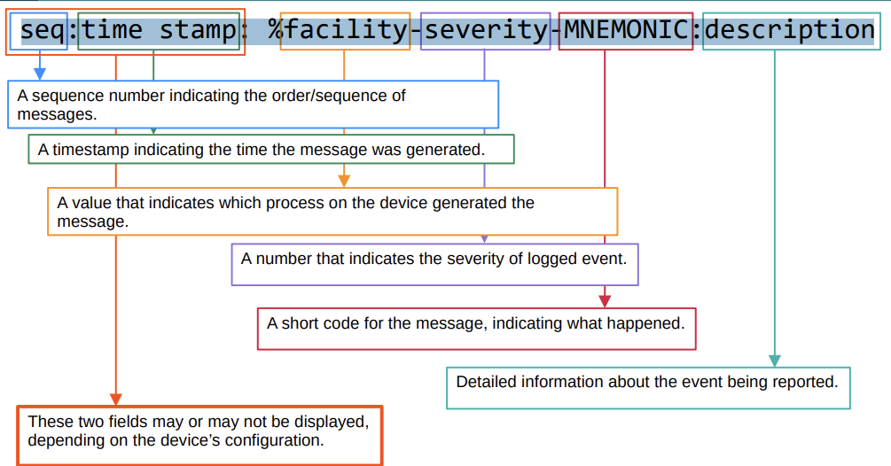
*Feb 11 03:02:55.304: %LINK-3-UPDOWN: Interface GigabitEthernet0/0, changed state to up
Syslog Severity Levels
| Level Number | Name | Description |
| 0 | Emergency | System is unusable |
| 1 | Alert | Immediate action needed |
| 2 | Critical | Critical condition |
| 3 | Error | Error condition |
| 4 | Warning | Warning condition |
| 5 | Notification | Normal but significant event |
| 6 | Informational | Informational messages |
| 7 | Debugging | Debugging messages |
💡 Every Awesome Cisco Engineer Will Need Ice cream Daily
| Feature | Syslog | SNMP |
| Purpose | Logs events and system messages | Monitors and manages network devices |
| Direction | Mostly device → server (one-way) | Manager ↔ Agent (two-way communication) |
| Data Type | Text-based messages (logs) | Structured data (counters, statuses, configs) |
| Event Reporting | Sends alerts automatically (logs) | Sends info when polled or traps when event occurs |
| Security | Basic (unless combined with secure transport) | SNMPv3 offers encryption and authentication |
Syslog Configuration
R1(config)# logging [server-ip]
R1(config)# logging 192.168.1.100
or
R1(config)# logging host [server-ip]
R1(config)# logging host 192.168.1.100
- By default, logging messages displayed in the CLI while you are in the middle of typing a command will result in something like this:
R1#show ip in
*Feb 11 09:38:41.607: %SYS-5-CONFIG_I: Configured from console by Rebar on
consoleterface brief
To prevent this, you should use the logging synchronous on the appropriate line.
R1(config)# no logging synchronous
FTP vs TFP
File Transfer Protocol: is a communications protocol used to send files from computer to computer, with one of them acting as the server.
TFTP(Trivial File Transfer Protocol) is a simplified version of FTP, it is designed to be easy and simple.
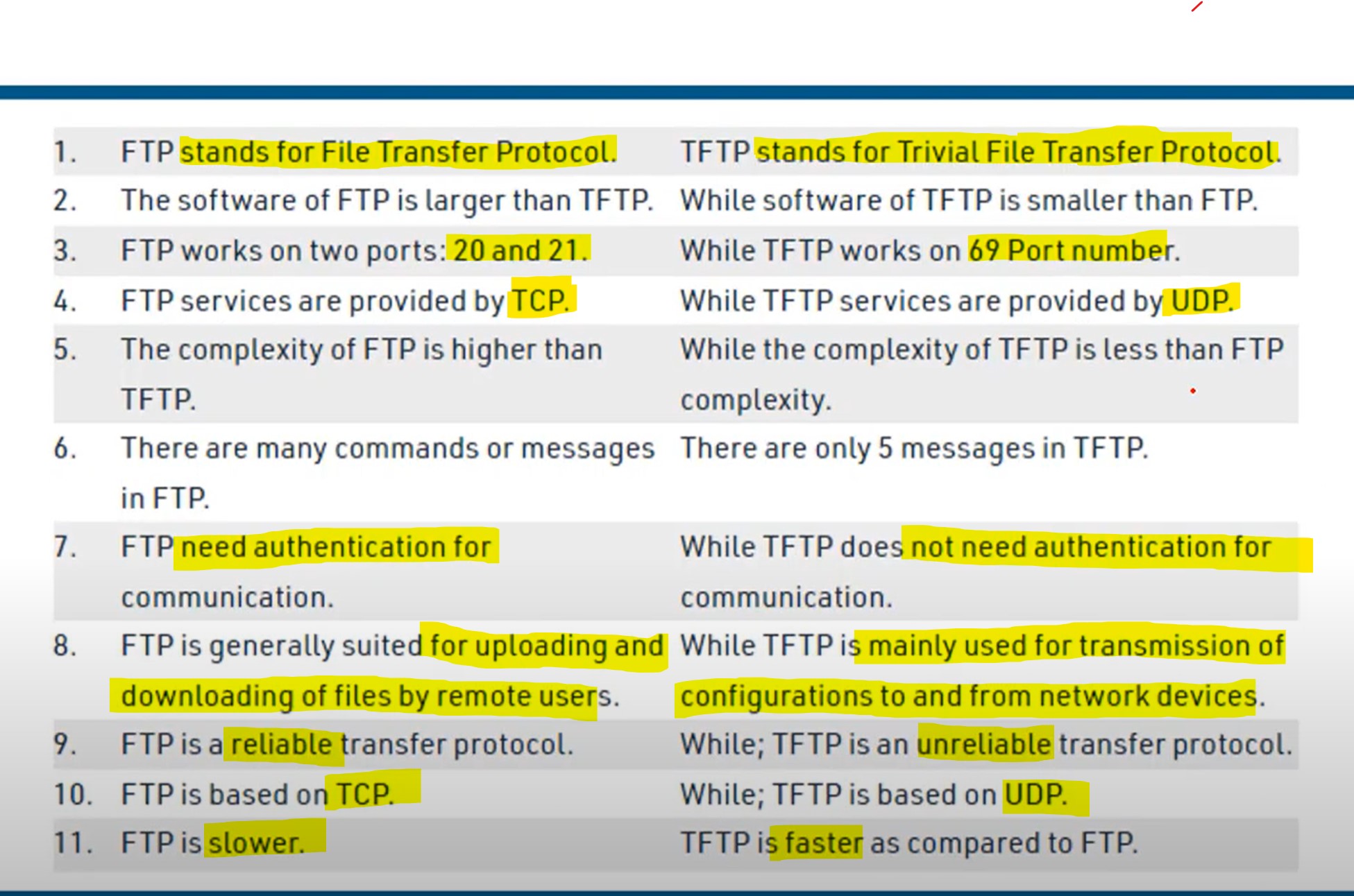
Security Architecture
Security Principles CIA
- Data confidentiality prevents the disclosure of information to unauthorized people, resources, or processes. It may require using cryptographic encryption algorithms such as AES to encrypt and decrypt data.
- Data integrity refers to the accuracy and consistency of data, ensuring that data is not tampered with by unauthorized users. It requires the use of cryptographic hashing algorithms such as SHA.
- Data availability ensures that information is accessible by authorized users when needed. It requires implementing redundant services, gateways, and links.
Data States
The cyberspace domain contains a considerable amount of critically important data. But in what state? The second dimension of the cybersecurity cube represents the three possible data states:
- Data in transit.
- Data at rest or in storage.
- Data in process.
Security Terms
| Term | Description |
| Assets | Anything of value to the organization, |
| Vulnerability | A weakness in a system or its design that could be exploited by threat hacker. |
| Exploit | A mechanism that takes advantage of a vulnerability |
| Spoofing | Impersonating a trusted entity. Fakes identity (IP, MAC, DNS, email, etc.) |
| Sniffing | Intercepting and monitoring network traffic |
| Mitigation | The process of taking countermeasures to reduce severity of a potential threat and risk. |
The most commonly known spoofing attacks are:
- IP Spoofing,
- Email Spoofing,
- DNS Spoofing,
- ARP Spoofing,
- GPS Spoofing
- Website Spoofing
- MAC Spoofing
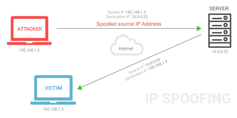
Denial-of-Service (DOS) Attacks
A Denial-of-service attack is an attack meant to shut down a machine or network, making it inaccessible to its intended users.
The most common DDoS attack occurs in the network layer (layer 3) and the transport layer(layer 4)**.** This is because these two layers are responsible for routing traffic and establishing connections between different networks. By flooding the network with traffic, the attacker can overwhelm the network and make it unavailable to legitimate users.
TCP SYN flood. → TCP three-way handshake: SYN | SYN-ACK | ❌ACK → The attacker sends countless TCP SYN messages to the target. → The target sends a SYN-ACK message in response to each SYN it receives. → The attacker never replies with the final ACK of the TCP three-way handshake. → The incomplete connections fill up the target’s TCP connection table. → The attacker continues sending SYN messages. → The target is no longer able to make legitimate TCP connections.
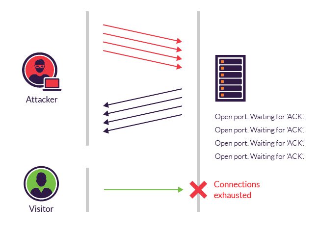
DHCP exhaustion attack (Spoofing)
● An attacker uses spoofed MAC addresses to flood DHCP Discover messages. ● The target server’s DHCP pool becomes full, resulting in a denial-of-service to other devices.
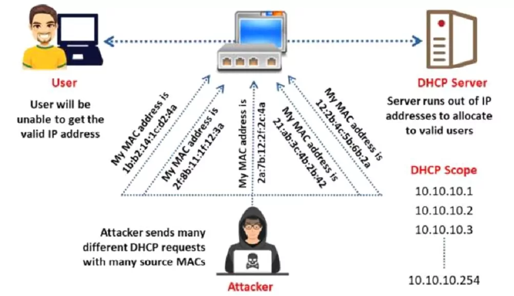
Man-in-the-middle-attacks
A man-in-the-middle attack is a type of eavesdropping attack where attackers interrupt an existing conversation or data transfer.
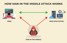
Buffer overflow
A buffer overflow is a type of software security vulnerability that can be exploited by an attacker to gain control of a computer system. It occurs when a program attempts to write more data to a buffer than the buffer can hold. The extra data overwrites adjacent memory locations, which can corrupt data or even crash the program.
Malware
Malware, short for malicious software, is a software program that is designed to harm a computer system or its users. It can be installed on a computer in a variety of ways, such as clicking on a malicious link, opening an infected attachment, or downloading a file from an untrusted source.
- A virus is malicious software that executes a specific, unwanted, often harmful function on a computer.
- A Trojan horse is harmful software that is disguised as legitimate software. They are spread through user interaction, such as opening email attachments or downloading a file from the Internet.
- A worm executes arbitrary code and installs copies of itself in the memory of the infected computer. The main purpose of a worm is to automatically replicate itself and spread across the network from system to system.
Human Vulnerability
Human vulnerability in the IT sector refers to how humans can be exploited by attackers to gain access to system data.
The most common Human vulnerability
- Phishing
- Social Engineering (refers to any attempt to manipulate people into doing something they would not normally do)
- Weak password
- Poor Security Practices: such as not using a firewall or antivirus software, and not patching software.
Firewall
In networking, a Firewall is a network device, either hardware or software-based, that monitors incoming and outgoing network traffic and permits or blocks data packets based on a set of rules.
Intrusion Detection System (IDS)
An intrusion detection system is a device or software application that monitors network traffic for malicious activity or policy violations. Any malicious activity or violation is typically reported or collected centrally using a security information and event management system.
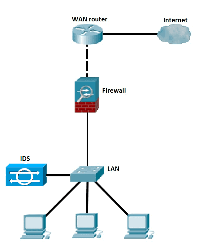
💡 Unlike IPS, a Network Intrusion Detection System (IDS) is not in line with the data path, so it can only alert and alarm on the detection of anomalies.
Intrusion Prevention System (IPS)
An Intrusion Prevention System works to detect and prevent identified threats. The IPS reports these events to system administrators and takes preventative action, such as closing access points and configuring firewalls to prevent future attacks. IPS solutions can also be used to identify issues with corporate security policies.
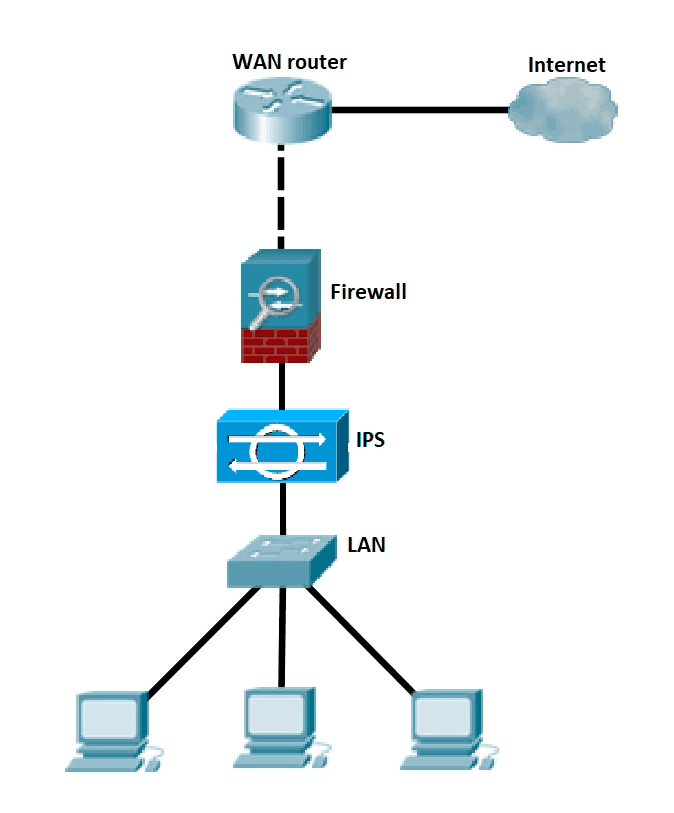
💡 Placement and configuration in inline mode and generally being in layer 2 after the firewall, inline mode traffic passes into one of the device’s Ethernet ports and out of the other
💡 Intrusion Prevention System must work efficiently to avoid decreasing network performance. It must be quick because exploits might occur at any time.
Cisco Next-Generation firewalls
- Next-generation firewalls (NGFWs) combine tr**aditional firewall technology with additional functionality, such as encrypted traffic inspection, intrusion prevention systems, anti-virus, and more. Most notably, it includes deep packet inspection (DPI). While basic firewalls only look at packet headers**, deep packet inspection examines the data within the packet itself, enabling users to identify, categorize, or stop packets with malicious data.
An NGFW typically has the following features
- Traditional Firewall: such as stateful filtering, NAT, PAT, and VPN termination.
- Application visibility and control (AVC): makes it possible to look deeply into the application layer data to defend against attacks that use random port numbers.
- Advanced Malware Protection: Block file transfers that would install malware and save copies of files for later analysis.
- Uniform resource locator(URL): URL filtering examines the URLs in each web request, categorizes the URLs, and either filters or rate-limits the traffic based on rules.
- NGIPS: Cisco’s NGFW products can also run their NGIPS Next-Generation Intrusion Prevention System feature along with the firewall.
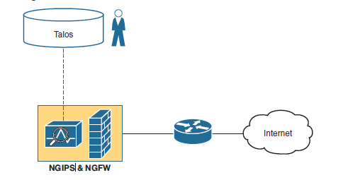
Switch Port Security
What is Port Security?
- Port Security is a layer two (layer-2) traffic control feature on Cisco Switches. It enables switch port configuration to allow only a specified number of source MAC addresses to use the port.
- An action will be taken if an unauthorized source MAC address enters the port. →The default action is to place the interface in an ‘err-disabled’ state.
- You can configure the allowed MAC address manually. →If you don’t configure it manually, the switch will allow the first source MAC address that enters the interface.
- You can change the maximum number of MAC addresses allowed.
Violation mode
- Protect: The switch port will permit traffic from known MAC addresses to continue sending while dropping traffic from unknown MAC addresses.
→ The interface is not disabled. → It does not generate syslog/SNMP messages for unauthorized traffic. → It does not increment the violation counter.
- Restrict: The switch port will permit traffic from known MAC addresses to continue sending traffic while dropping traffic from unknown MAC addresses.
→ The interface is not disabled. → It generates syslog/SNMP messages for unauthorized traffic. → It increments the violation counter by 1 for each unauthorized frame.
- Shut Down: The switch port shuts down immediately if unauthorized access is done.
→ It generates syslog/SNMP messages for unauthorized traffic. → It increments the violation counter by 1 for each unauthorized frame. → The switch port will be placed in the err-disabled state ( this state until manually removed by the administrator by performing a (no shutdown) command).
💡 Shut down is a default switch port violation mode.
Errdisbale is a feature that automatically disables a port on a Cisco Catalyst switch
Enabling Port Security
- Port Security can be enabled with default parameters by issuing a single command on an interface.
switch(config)# interface f0/3 (selected interface)
switch(config-if)# switchport port-security  (switch port security enabled)
or
switch(config-if)# switchport port-security mac-address 000a.000a.000a (switchport manually adding mac address)


switch(config-if)# switchport port-security violation [mode] (Changing viloation mode shutdown is defualt)

switch# show port-security interface f0/3
How to reset an interface that is disabled due to a violation of port security
- Disconnect the unauthorized device.
- shutdown and then no shutdown the interface
SW1(config)#interface g0/1
SW1(config-if)#shutdown
SW1(config-if)#no shutdown
2- By using the command below, you can reset your connection status from down to up.
Switch(config)# errdisable recovery cause psecure-violation
Switch(config)#errdisble recovery interval 60
Please note that this command does not work in Packet Tracer!
| interval 30 | It means when the port shuts down due to shutdown violation mode recovery the port to upstate after n seconds |
💡 Every 5 minutes (by default), all err-disabled interfaces will be re-enabled if err-disable recovery has been enabled for the cause of the interface’s disablement.
Sticky
Switch Port Security with Sticky MAC Addressing is a Cisco switch feature that allows a port to dynamically learn MAC addresses and automatically convert them to static secure MAC addresses.
- For example, if the user provides a maximum limit of 2 the the first two MAC addresses learned on that port will be placed in the running configuration after the 2nd learned MAC address. If the 3rd MAC address wants to access, then the appropriate action will be taken according to the violation mode applied.
Switch(config)# interface FastEthernet0/1
Switch(config-if)# switchport mode access
Switch(config-if)# switchport port-security
Switch(config-if)# switchport port-security maximum 1
Switch(config-if)# switchport port-security mac-address sticky [automatically mac address of the first desvice]

or

Switch(config-if)# switchport port-security mac-address sticky **000a.000a.000a** [static set mac address as sticky]


Switch(config-if)# switchport port-security violation shutdown
This:
- Enables port security.
- Allows only 1 MAC address.
- Learns and sticks the MAC of the connected device.
- Shuts the port if a violation occurs.
🧠 Tip:
After learning MACs via sticky, you can save them to the startup config using:
Switch# copy running-config startup-config
Otherwise, they will be lost on reboot.
MAC Address Table
Secure MAC addresses will be added to the MAC address table like any other MAC address. → Sticky and Static secure MAC addresses will have a type of STATIC → Dynamically-learned secure MAC addresses will have a type of DYNAMIC → You can view all secure MAC addresses with show mac address-table secure command
SW1#show mac address-table secure
Mac Address Table
-------------------------------------------
Vlan Mac Address Type Ports
---- ----------- -------- -----
1 000a.000a.000a STATIC Gi0/1
How to remove the MAC address from the MAC table when it has not been active for a while
Switch(config-if)switchport port-security aging time 3 (time in minutes)
After 3 minutes of inactivity, the MAC address was removed from the MAC address table, and then the switch was ready to add another MAC address to the MAC address table.
💡 By default, secure MAC addresses will not ‘age out’ (Aging Time : 0 mins)
LAB
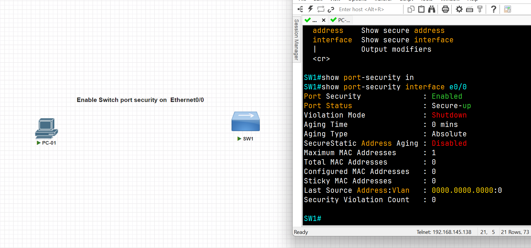
SW1(config)#int e0/0
SW1(config-if)#switchport port-security
Command rejected: Ethernet0/0 is a dynamic port.
SW1(config-if)#switchport mode access
SW1(config-if)#switchport port-security
SW1(config-if)#exit
SW1(config)#exit
SW1#show port-security interface e0/0
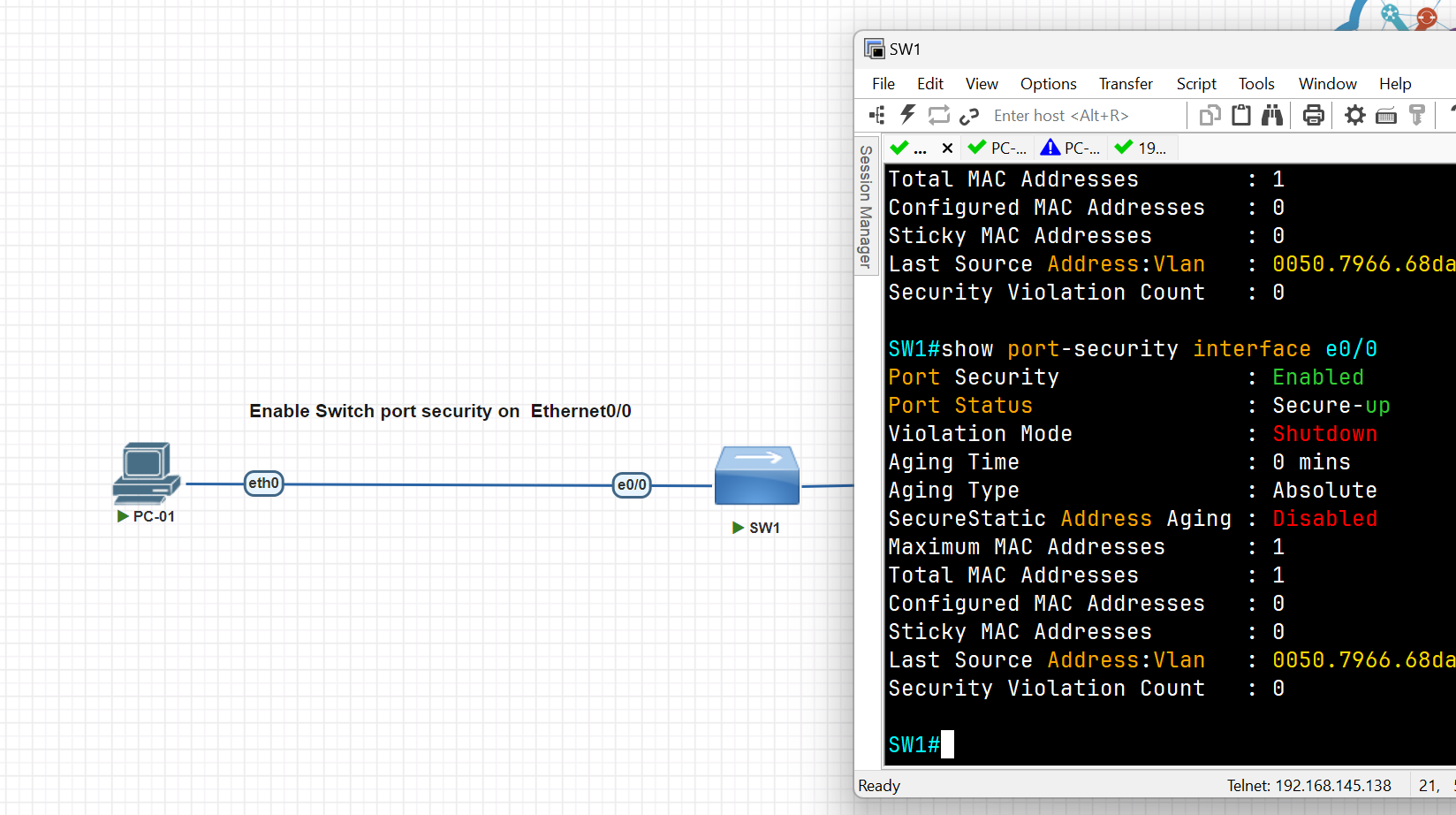
SW1#
SW1#conf t
SW1(config)#int eth0/2
SW1(config-if)#switchport mode access
SW1(config-if)#switch port-security maximum 1
SW1(config-if)#switchport port-security mac-address sticky 0050.7966.68dc
SW1(config-if)#switchport port-security violation shutdown
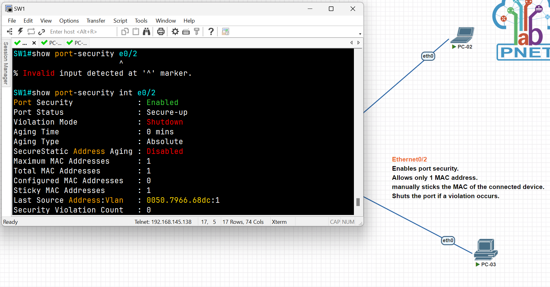
SW1#show port-security
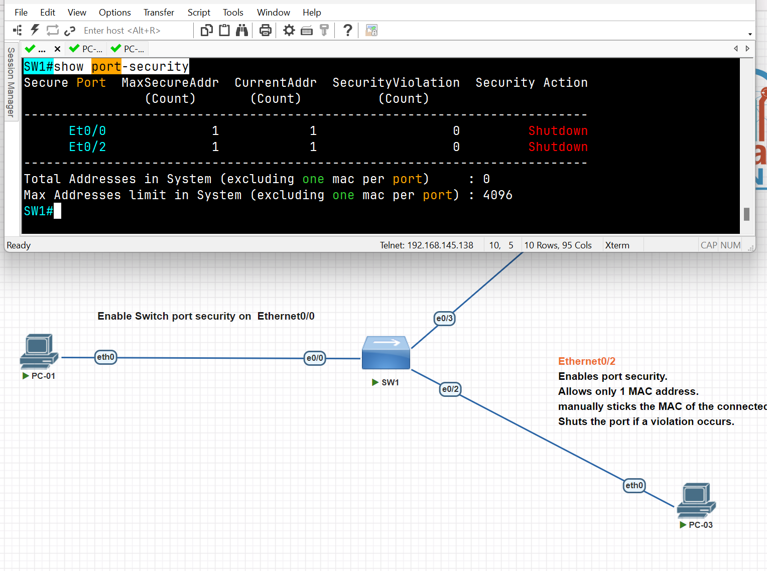
DHCP Snooping and ARP Inspection
DHCP Snooping is a security technology on a layer 2 network switch that can prevent unauthorized DHCP servers from accessing your network, It is a protection from untrusted hosts that want to become DHCP servers. DHCP snooping works as protection from man-in-the-middle attacks. DHCP itself operates on layer 3 of the OSI model, while DHCP snooping operates on layer 2 devices to filter the traffic that is coming from DHCP clients.
- DHCP snooping only filters DHCP messages. Non-DHCP messages aren’t affected.
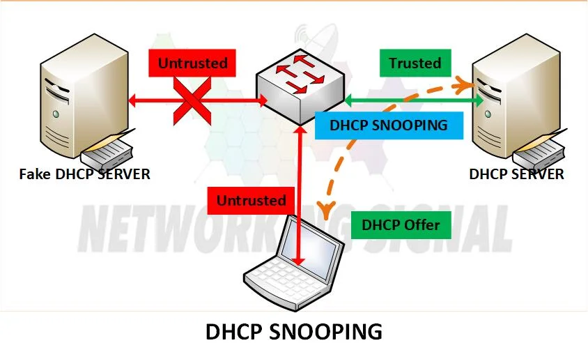
DHCP exhaustion attack (Spoofing)
● An attacker uses spoofed MAC addresses to flood DHCP Discover messages. ● The target server’s DHCP pool becomes full, resulting in a denial-of-service to other devices.
the first Step is to trust the interface
Switch(config)#interface fastEthernet 0/1
Switch(config-if)#ip dhcp snooping trust
Second Step Enable DHCP Snooping
Switch(config)#ip  dhcp snooping
Switch(config)#no ip  dhcp snooping information option ( for now disable it)
Switch(config)#ip dhcp snooping vlan 1 (select the VLAN you want to apply snooping for now we select Vlan 1)
Third Stage verification
Switch#show ip dhcp snooping
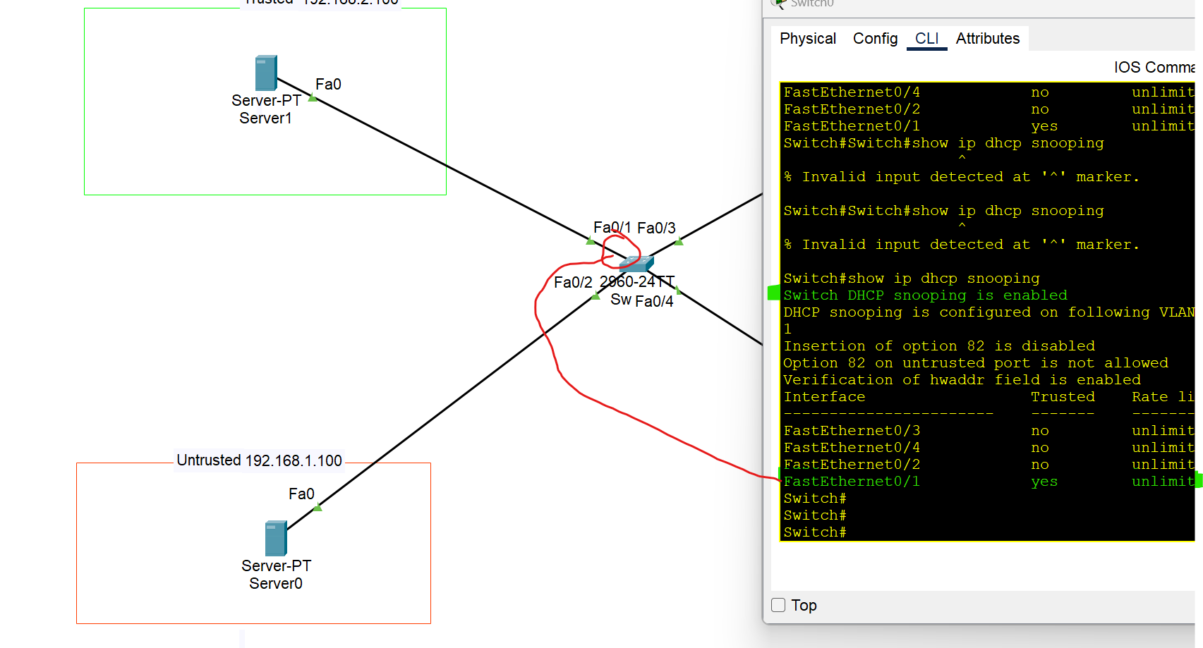
Switch#show ip dhcp snooping binding
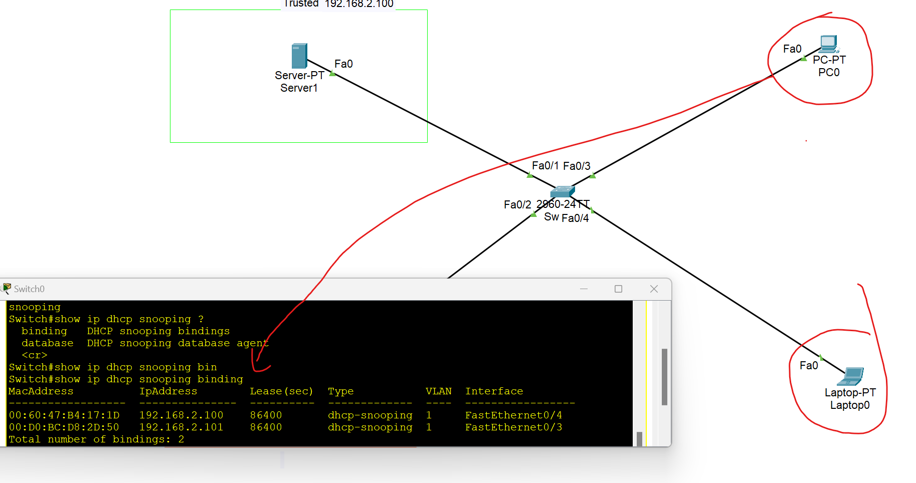
Displays a list of IP-to-MAC address bindings dynamically learned via DHCP snooping.
Dynamic ARP Inspection
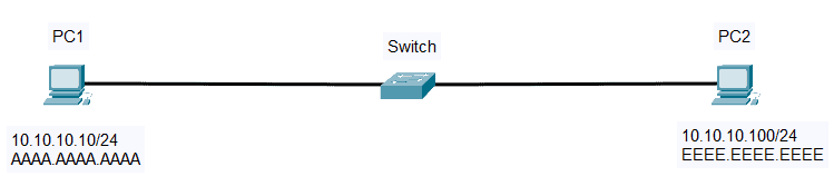
- First, PC 1 checks its ARP table for PC2’s IP address (10.10.10.100)
- If there is no cache, PC1 will send ARP Request and broadcast message (Source: AAAA.AAAA.AAAA, destination: FFFF.FFFF.FFFF) to all hosts on the same subnet.
- All hosts will receive the ARP request, but only PC2 will reply. PC2 will send an ARP reply containing its own MAC address (EEEE.EEEE.EEEE).
- PC1 receives the MAC Address and saves it to its ARP Table.
ARP Inspection
Dynamic ARP Inspection (DAI) is a security feature that rejects invalid and malicious ARP packets(ARP spoofing) . The feature prevents a class of man-in-the-middle attacks. When DAI is enabled, the switch drops ARP packets if the sender MAC address and sender IP address do not match any entry in the DHCP snooping bindings database.
- DAI only filters ARP messages. Non-ARP messages aren’t affected.
- All ports are untrusted by default. → Typically, all ports connected to other network devices (switches, routers) should be configured as trusted, while interfaces connected to end hosts should remain untrusted.
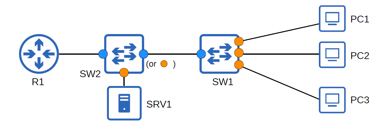
- Dynamic ARP Inspection monitors ARP packets on untrusted ports and validates them against a trusted source, usually the DHCP snooping binding table. If an ARP packet is invalid or doesn't match the table, it is dropped.
- It relies on DHCP snooping to verify IP-MAC bindings.
- Helps maintain integrity in Layer 2 switched networks.
### Why Do We Need Dynamic ARP Inspection (DAI)?
You may be asking why we need Dynamic ARP Inspection (DAI). In our first example, a rogue peer, PC3, is connected to one of the switch ports. PC3 can send a Gratuitous ARP or an ARP Reply that was not prompted by an ARP Request to update the ARP mapping of the other hosts on the network.
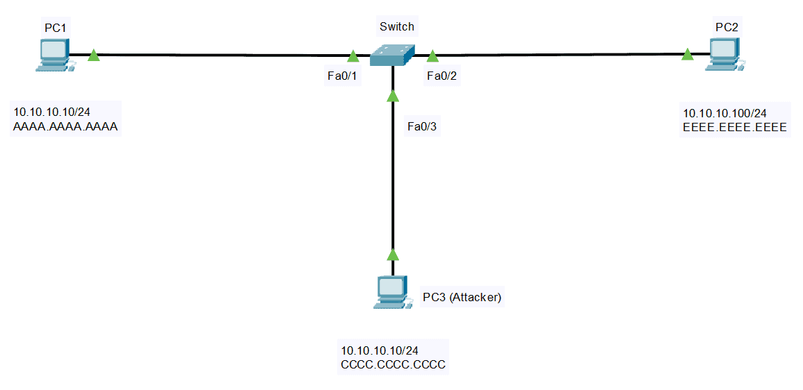
Unknowingly, PC2 will update its ARP Cache and change the MAC address of PC1 to the MAC address of PC3. Same with the other direction, PC3 can spoof PC2 by lying about its MAC address. This attack, or ARP spoofing, is also called a Man-in-the-Middle attack.
Enable ARP Inspection
Switch(config)#IP arp inspection vlan 1
Dynamic ARP Inspection Verification
Switch#show ip arp inspection
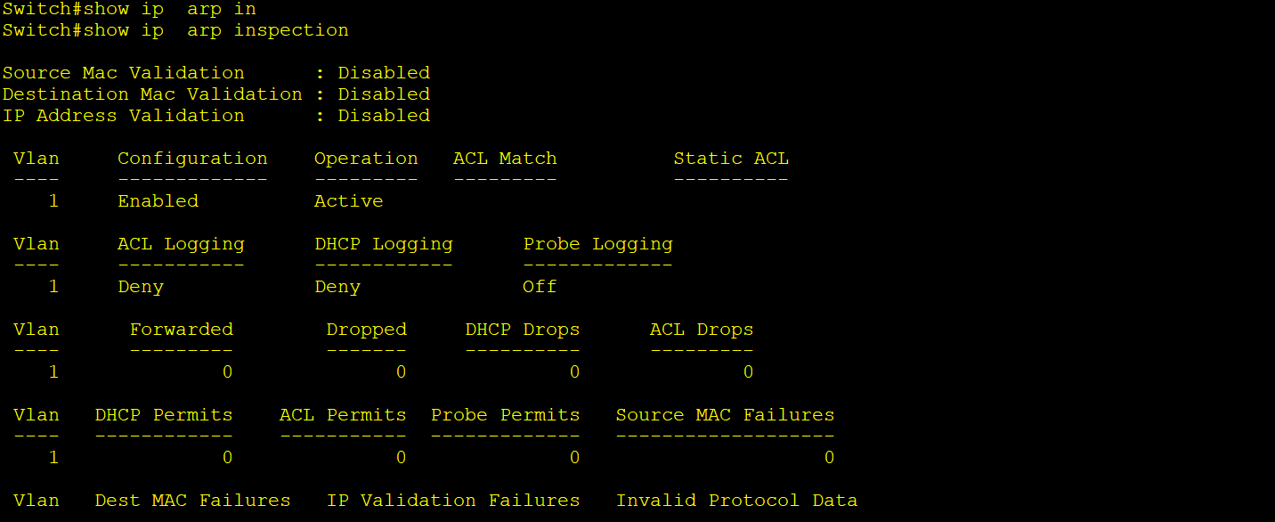
Switch#show ip  arp inspection statistics

Switch#show ip arp inspection interfaces
To Trust Interfaces between network devices should be trusted
Switch(config)#interface fastEthernet 0/1
Switch(config-if)#ip arp inspection trust
Switch(config)#ip arp inspection validation [des-mac, ip, src-mac]
How to Detect an ARP Cache Poisoning Attack
arp -a
The output will look something like this:
Internet Address    Physical Address

**192.168.5.1        00-14-22-01-23-45**
192.168.5.201      40-d4-48-cr-55-b8
192.168.5.202      **00-14-22-01-23-45**
If the table contains two different IP addresses that have the same MAC address, this indicates an ARP attack is taking place. Because the IP address 192.168.5.1 can be recognized as the router, the attacker’s IP is probably 192.168.5.202.
no
NAT (Network Address Translation)
- NAT (Network Address Translation) is a process of mapping multiple private addresses inside a local network to a public address.
Advantages of NAT
- Connecting a large number of hosts to the global Internet using a smaller number of public (external) IP addresses, thereby conserving IP address space
- It provides privacy as the device’s IP address, sending and receiving the traffic, will be hidden.
- Eliminates address renumbering when a network evolves. (If the number of private IPs increased or decreased, it didn’t affect the Public IP)
Disadvantages of NAT
- Translation results in switching path delays**.**
- Certain applications will not function while NAT is enabled. (For example, when gamers have an issue with NAT, they prefer NAT Type 2 to NAT Type 3 for gaming)
- Complicates tunneling protocols such as IPsec.
Type of NAT
- Static NAT: Translate one private IP to one public IP(one-to-one mapping).

- Dynamic NAT: Private IP addresses are mapped to the pool of public IP addresses. If the IP addresses from the pool are not free, then the packet will be dropped.
At this point, all the shared IP addresses have been used. When Host D (10.7.7.74) attempts to initiate a connection to 86.8.6.9, the packet is dropped because there are no available public IP addresses on the router.
Therefore, using PAT is the best solution,
- Port Address Translation: one public address is used for all internal devices, but a different port is assigned to each private IP address. Also known as NAT overload.
As you can see, we can use one public IP by PAT, many devices can use the same public IP address, and PCs B and C can access the server through different port numbers. Using one Public IP address to send out a large range of private IPs with different ports
NAT Terminology
Inside Local: The private IP address of your device inside the local network.
Inside Global: The public IP address assigned by NAT for your internal host to use outside.
Outside Local: the IP addresses of the outside host, from the perspective of the local network (Public IP).
Outside Global: Outside global address is the public IP address assigned to the end device on the other network to communicate with other devices on the internet.
| Inside Local address | Outside Local Address | Inside Global address | Outside Global Address |
| 192.168.1.10/20 | 111.1.1.1:80 | 200.1.1.1 | 111.1.1.1:80 |
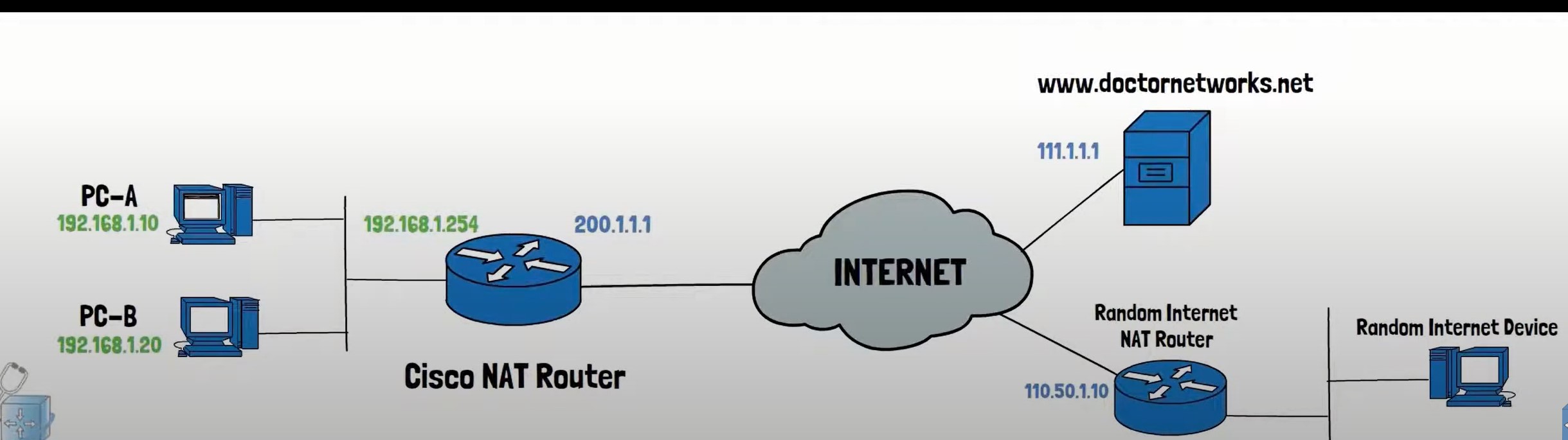
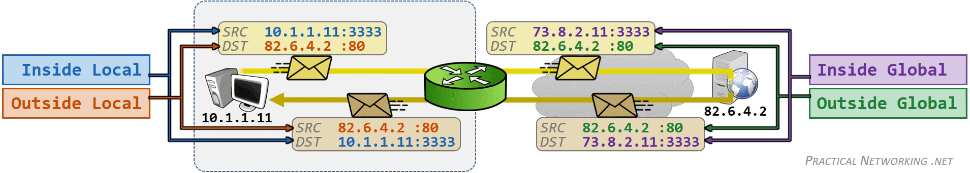
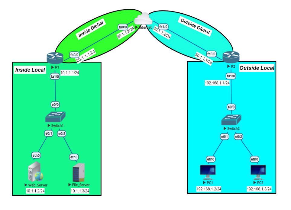
Static NAT Configuration
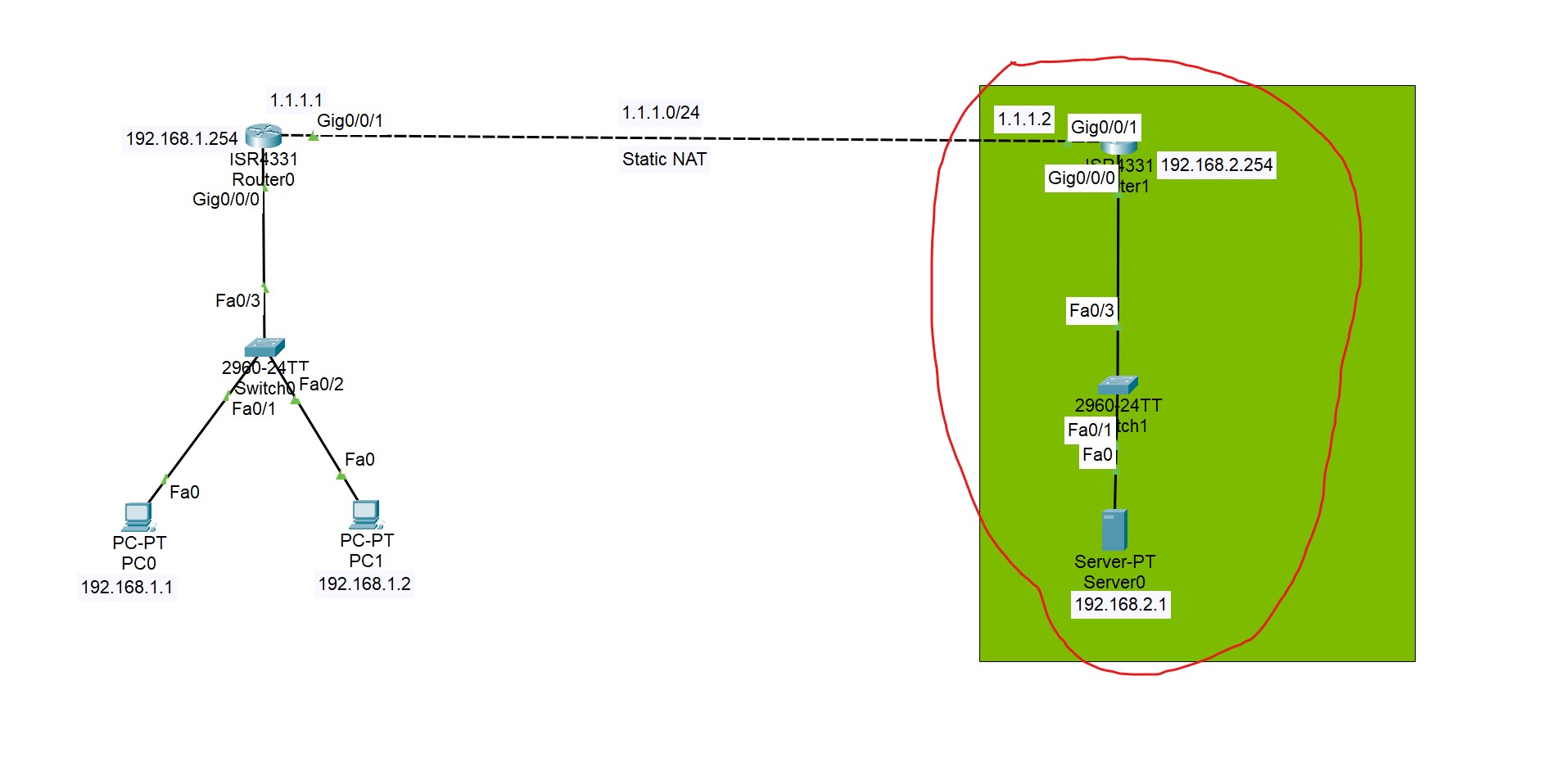
In this lab, static NAT is configured on the selected area, and Global IP addresses are translated to Local IP addresses based on the static mapping of these IP addresses.
The first step define which interface is Inside or Outside.
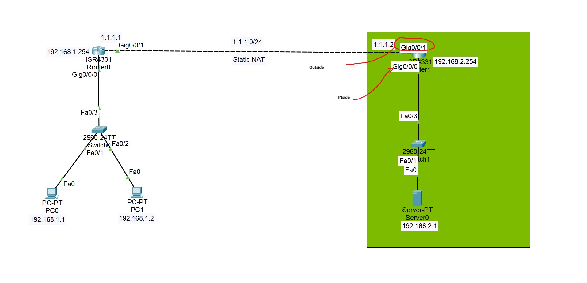
Router(config)#interface gigabitEthernet 0/0/1
Router(config-if)#ip nat outside (interface connected to the external network)

Router(config)#interface gigabitEthernet 0/0/0
Router(config-if)#ip nat inside
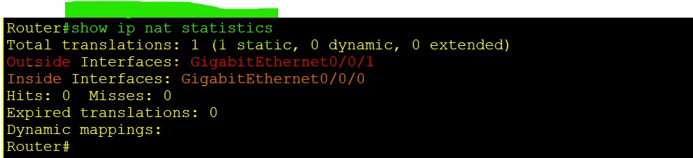
Router(config)#ip nat ([inside or outside] dway awa alet nawa bo  darawa yan darawa bo nawawa nat akit)
Router(config)#ip nat inside (wata nawaw la darawa bbinret) source [static or list] (now in this case we have a one static IP)
Router(config)#ip nat inside source static 192.168.2.1 [Inside local IP address] 1.1.1.2 [your public ip address operated by you]
Router(config)# ip nat  inside source static 192.168.2.1 1.1.1.2 [final command should be like this]
Router#show ip nat translations
Pro  Inside global     Inside local       Outside local      Outside global
---  1.1.1.2           192.168.2.1        ---                ---
As you can see, we have a global IP address that NATs to a local IP address.
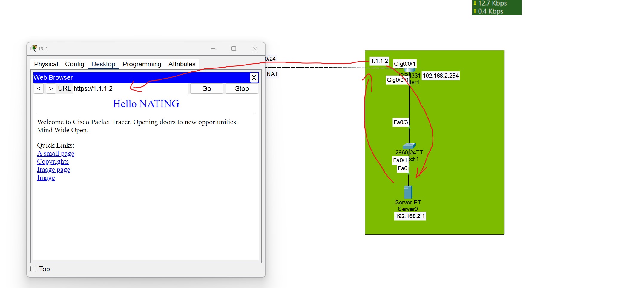
Enter the public IP address of the server in the client browser you can see the server content, because the public IP is translated to the local address of the server.
To verify these NAT translations:
R1#show ip nat translations
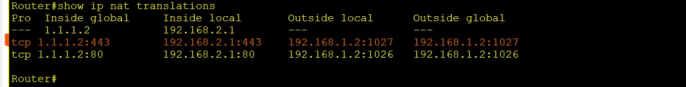
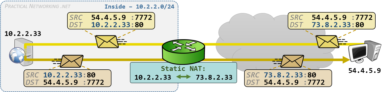
💡 If you have already statically mapped a private IP address to a public IP address, if you try to map another private IP to the same Public IP, the command will be rejected.
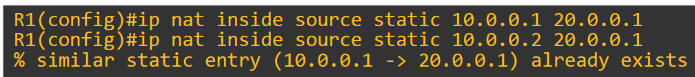
Dynamic NAT and PAT
- Configure Inside and Outside Interfaces.
- Create an Access List to Match Inside Hosts.
- Define a NAT Pool.
- Bind the Access List to the Pool.
PAT Configuration
- PAT Configuration has the same configuration as Dynamic NAT, just add overload to the end.
- There's no need to define a pool for a single IP.
ip nat inside source list 1 interface fa0/1 [Inside Gloabal Interface] overload
This simpler and directly ties NAT to the interface’s IP
- In case of using a pool, you can use the pool like this:
ip nat pool SINGLEPAT 1.1.1.1 1.1.1.1 netmask 255.255.255.0
First, we need to configure the router’s inside and outside NAT interfaces:
Router(config)#interface gigabitEthernet 0/0/0
Router(config-if)#ip nat inside
Router(config)#interface gigabitEthernet 0/0/1
Router(config-if)#ip nat outside
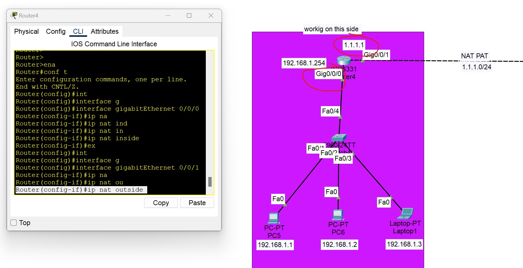
We need to configure an ACL that includes a list of the inside source addresses that will be translated.
Router(config)#access-list 1 permit 192.168.1.0 0.0.0.255
We need to configure a pool of global (Public) IP addresses available on the outside interfaces
Router(config)#ip nat pool [Pool Name] [Start IP address] [End IP address] netmask [Subnet mask]
Router(config)#ip nat poo1l nat-pool 1.1.1.10 1.1.1.20  netmask 255.255.255.0
[Start IP address] [End IP address] is the range of IP addresses you purchased from your ISP. In this example, we purchased 10 IPs from the ISP.
Lastly, we need to enable Dynamic / PAT NAT
Router(config)#ip nat inside source list [access list name or number] pool [pool name]
Router(config)#ip nat  inside source list 1 pool nat-pool  (**without overload command it be dynamic NAT**)
**Router(config)#ip nat  inside source list 1 pool nat-pool overload [PAT]**
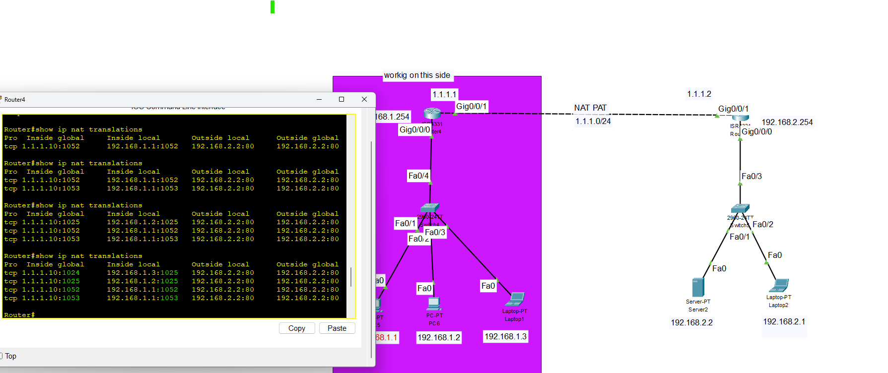
As you can see, different port numbers are used for NAT
QOS Quality of Service
What is QOS?
QoS (Quality of service) refers to the set of technologies used to manage network traffic to meet the service requirements of specific applications, especially real-time ones like:
- Voice over IP (VoIP)
- Video conferencing
- Online gaming
Why is QoS Important?
Without QoS, all traffic is treated equally, leading to congestion and poor performance of delay-sensitive traffic.
Visualizing network bandwidth with and without QOS
QOS Queueing
QoS Queuing is a method used in Quality of Service (QoS) to manage how packets are stored and transmitted through network devices (like routers and switches) when there is congestion. When multiple packets compete for the same output interface, queuing (Priority Queuing) decides which packets go first and which must wait or get dropped. Queues are high-performance memory buffers in routers and switches. When a packet is assigned a higher priority, it is moved to a dedicated queue that pushes data faster rate
- If the queue is full, new packets will be dropped, this is called a tail drop.
- Tail drop is harmful because it can lead to TCP Global Synchronization.
Type of Network Traffic
QoS is used to manage the following characteristics of network traffic:
- Bandwidth is the speed of the link, usually measured as bits per second(bps). QoS can tell a router how to use bandwidth. For example, we can configure the router so that one queue gets 50% of the bandwidth, queue two gets 20% of the bandwidth, and queue three gets 30% of the bandwidth.
- Delay(latency)
The amount of time it takes for packets of data to travel from source to destination is = one-way delay.
The amount of time it takes for packets of data to travel from source to destination and return =two-way delay.
- Jitter: the variation in one-way delay between packets sent by the same application. For example, The first packet is sent and the second packet is sent after 50 milliseconds (MS), the time it takes for the second packet to be sent after the first packet was sent is the jitter and, it is 50 Ms. which can result in packets arriving late and out of the sequence. This can cause distortion or gaps in audio and video being delivered. (A better connection should have less jitter)
- Loss:
The percentage of packets sent that do not reach their destination.
can be caused by Faulty Hardware, Software Issues, or Network Congestion.
It can also be caused when a device’s packet queue gets full and the device starts discarding packets.
The standard recommendation for acceptable interactive voice:
| One-way-delay | 150 ms or less |
| Jitter | 30 ms or less |
| Loss | 1% or less |
- If these standards are not met, there could be a noticeable reduction in the quality of the phone call
Quality of Service (QOS) Mechanism
- Classification: organizes network traffic (packets) into traffic classes (categories) (e.g., VoIP, video, data).
- Marking: Labeling packets (e.g., using DSCP or CoS) so they can be prioritized.
- Queueing-Congestion management: Prioritize the transmission of each packet by queueing on each interface. (enabling queueing and allowing high priority can join the queue quickly).
- Congestion Avoidance: Techniques like WRED to drop low-priority packets to avoid tail drop.
- Policing is a QoS feature that monitors and controls traffic rates on an interface. It compares traffic to a set rate called the CIR (Committed Information Rate). If traffic exceeds this rate, the excess packets are either dropped or remarked with a lower QoS value.
- Shaping is a QoS feature that controls traffic rate by buffering excess packets instead of dropping them. When traffic exceeds the configured CIR (Committed Information Rate), the shaper holds the packets in a buffer and sends them later when bandwidth becomes available.
💡 - Instead of waiting for policer of the ISP to drop your traffic.
We can shape the outgoing traffic towards the ISP so that they do not drop it.
We can use shaping to make sure that everything will be sent until its buffer is full.
- Instead of waiting for policer of the ISP to drop your traffic.
- We can shape the outgoing traffic towards the ISP so that they do not drop it.
- We can use shaping to make sure that everything will be sent until its buffer is full.
CBWFQ (Class-Based Weighted Fair Queuing) is a popular scheduling method that uses a weighted round-robin scheduler while guaranteeing each queue a certain percentage of the interface’s bandwidth during congestion.
Which two QoS tools provide congestion management?
- CBWFQ
- PR
Which IP header field is changed by a Cisco device when QoS marking is enabled?
- Type of Service.
QOS Quality of Service Implementation
Classification:
Router(config)#class-map Web-Traffic  [class-map name]
Router(config-cmap)#match protocol HTTP(which protocol used)
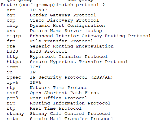
Policing:
Router(config)#policy-map  web-traffic-policy [policy name]
Router(config-pmap)#class web-traffic   [assign the class to the policy]
Router(config-pmap-c)#bandwidth 1000  [in this rule we set 1mbps to web traffic]
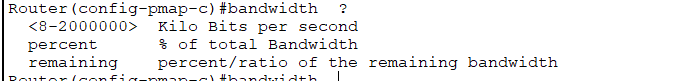
### Applying to the interface
Router(config)#interface gigabitEthernet 0/0/1
Router(config-if)#service-policy output  web-traffic-policy [policy name]
| Input | Assign policy-map to the input of an interface |
| output | Assign policy-map to the output of an interface |
IP Services
Networks need redundant links and should always be designed to maximize availability. A router's power supply might fail, a cable could break, or a switch might lose power.
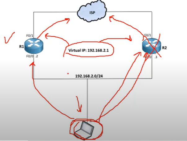
For example, if one of the routers goes down, a backup router can take over and continue forwarding packets to their destination.
💡 To achieve redundancy, we should have a Virtual IP as a gateway to switch between routers.
First Hope Redundancy Protocol
A first Hope Redundancy Protocol(FHRP) is a layer 3 protocol designed to protect and ensure the availability of the gateway for end devices on a local subnet by allowing two or more routers to provide backup for that address.
Type of FHRP protocols:
- Hot Standby Router Protocol (HSRP)
- Virtual Router Redundancy Protocol (VRRP)
- Gateway Load Balancing Protocol(GLBP)
How FHRP Works (Basic Idea)
- A virtual IP is configured on the two routers.
- One Router is active (forwarding traffic), and others are in standby or backup mode.
- Each network host is configured to use the virtual IP as their default gateway.
- If the active router fails, the standby becomes the next active router.
HSRP
Hot Standby Router Protocol (HSRP) is a Cisco proprietary protocol that provides redundancy for a local subnet. It is an active/standby router model.
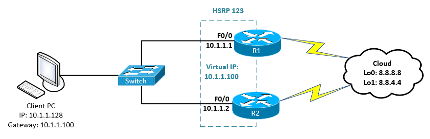
VRRP
Virtual Router Redundancy Protocol (VRRP) is very similar to HSRP and can be used to create a virtual gateway. It is a Master/Backup router model and is more usable by companies because it is a global protocol.
GLBP
Gateway Load Balancing Protocol(GLBP): protects data traffic from a failed router or circuit, like (HSRP) and (VRRP), while allowing packet load sharing between a group of redundant routers.
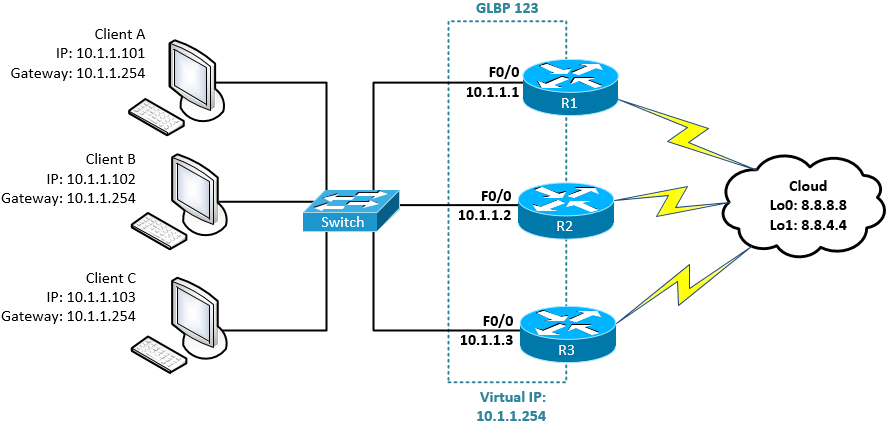
As you can see, all routers are working and forwarding packets, and none of them are standing by.
| HSRP | VRRP | GLBP |
| Cisco Propriety | Standardized | Cisco propriety |
| Active and Standby mode only. | Active and Standby mode only. | Multiple routers pass traffic thus achieving load balancing. |
| Must configure a separate IP for the Virtual. | Virtual IP can be the same as the physical IP of one of the routers | Most configure separate IPs for the Virtual |
| Default Priority = 100 | Default Priority = 100 | Default Priority = 100 |
| Higher priority (above 100) makes the router active. otherwise, a Higher IP makes the router active. | Higher priority (above 100) makes the router active. otherwise, a Higher IP makes the router active. | Higher priority (above 100) makes the router the primary forwarder. otherwise, a higher IP makes the router the primary forwarder |
| Tracking support(e.g. interface state, routing info, reachability of remote host, etc.) | Tracking support(e.g. interface state, routing info, reachability of remote host, etc.) | Tracking support(e.g. interface state, routing info, reachability of remote host, etc.) |
| support IPV6 | No support for IPv6 on the original VRRP implementation. however, VRRP v3 supports it | Support IPV6 |
| Support timer and delay adjustments for failover | Support timer and delay adjustment for failover | Support timer and delay adjustment for failover |
VRRP Labs
Router(config)#interface fa2/0
Router(config-if)#vrrp 1 [<1-255>  Group number] ip  192.168.1.1 (virtual IP)
Router(config-if)#vrrp 1 priority 150 (1 to 254) [by default is 100 we change it to 150 to ensure it remains as a master]
Verify the configuration
Master#show vrrp
Master#show vrrp brief
Track Object
- First, create object tracking and select which interface to track.
Router(config)#track 1 <1-500>Tracked object ( the what you want to track)
Router(config)#track 1  interface fastEthernet 1/0  [IP or line-protocol]
Router(config)#track 1 interface fa0/0 line-protocol
| interface | Select an interface to track |
| IP | IP protocol |
| List | Group objects in a list |
| sub-object | Stub tracking object |
| line-protocol | When the interface gets down physically or logically, it represents as a down |
- Second, apply the created track to the VRRP.
Router(config)#interface fa 2/0
Router(config-if)#vrrp 1 track 1 (Id of the created track you want to apply to the VRRP)
Router(config-if)#vrrp 1 track 1 decrement 50 [decreaament the priority]
VRRP

In this scenario, two routers are connected to the ISP. We will proceed with configuring VRRP, designating one router as the master and the other as the backup.
Basic IP Configuration
PC1> ip 192.168.1.2 255.255.255.0 192.168.1.1
Master#conf t
Master(config)#
Master(config)#int fa 1/0
Master(config-if)#ip address 192.168.1.4 255.255.255.0
Master(config-if)#no shut
Master(config-if)#exit

Master(config)#int fa0/0
Master(config-if)#ip address 8.8.8.2 255.255.255.0
Master(config-if)#no shutdown
Master(config-if)#exit
Master(config)#exit
Master#wr
BackUp#conf t
BackUp(config)#int fa1/0
BackUp(config-if)#ip address 192.168.1.5 255.255.255.0
BackUp(config-if)#no shutdown
BackUp(config-if)#exit

BackUp(config)#int fa0/0
BackUp(config-if)#ip address  4.2.2.2 255.255.255.0
BackUp(config-if)#no shutdown

BackUp(config-if)#exit
BackUp(config)#exit
BackUp#wr
ISP#conf t
ISP(config)#int fa 1/0
ISP(config-if)#ip address 8.8.8.1 255.255.255.0
ISP(config-if)#no shut
ISP(config-if)#exit

ISP(config)#int fa0/0
ISP(config-if)#ip address 4.2.2.1 255.255.255.0
ISP(config-if)#no shut
ISP(config-if)#exit
ISP(config)#exit
ISP#wr
OSPF Configuration
Master#conf t

Master(config)#router ospf 1
Master(config-router)#net
Master(config-router)#network 192.168.1.0 0.0.0.255 area 0
Master(config-router)#network 8.8.8.0 0.0.0.255 area 0
Master(config-router)#passive-interface fa1/0
Master(config-router)#exit
Master(config)#exit
Master#wr
BackUp#conf t
BackUp(config)#router ospf 1
BackUp(config-router)#network 192.168.1.0 0.0.0.255 area 0
BackUp(config-router)#network 4.2.2.0 0.0.0.255 area 0
BackUp(config-router)#passive-interface fa1/0
BackUp(config-router)#exit
BackUp(config)#exit
BackUp#wr
ISP#conf t
ISP(config)#router ospf 1
ISP(config-router)#network 8.8.8.0 0.0.0.255 area 0
ISP(config-router)#network 4.2.2.0 0.0.0.255 area 0
ISP(config-router)#exit
ISP(config)#exit
ISP#wr
VRRP Master Router Configuration
Master#conf t
Master(config)#int fa1/0
Master(config-if)#vrrp 1 ip 192.168.1.1
Master(config-if)#vrrp 1 priority 150
Master(config-if)#vrrp 1 preempt
Master(config-if)#exit
Master(config)#exit
Master#
VRRP Master Router Configuration
Master#show vrrp
Master#show vrrp brief
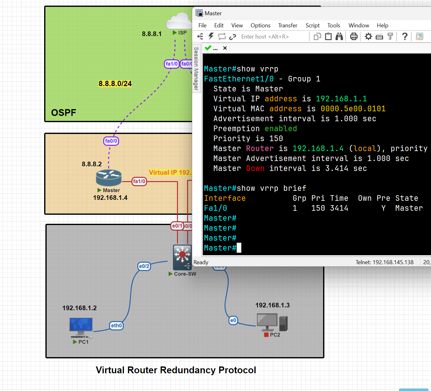
VRRP Master Router Configuration
BackUp#conf t
BackUp(config)#int fa1/0
BackUp(config-if)#vrrp 1 ip 192.168.1.1
BackUp(config-if)#vrrp 1 preempt
BackUp(config-if)#exit
BackUp(config)#exit
BackUp#wr
Apply Tracker to the specific interface
Master(config)#track 1 interface fa0/0 line-protocol
Mapping Tracker to the VRRP
Master(config)#int fa1/0
Master(config-if)#vrrp 1 tra
Master(config-if)#vrrp 1 track 1
Master(config-if)#vrrp 1 track 1 decrement 60 [ decrement  Priority decrement]
Testing tracker and switching traffic from master to backup
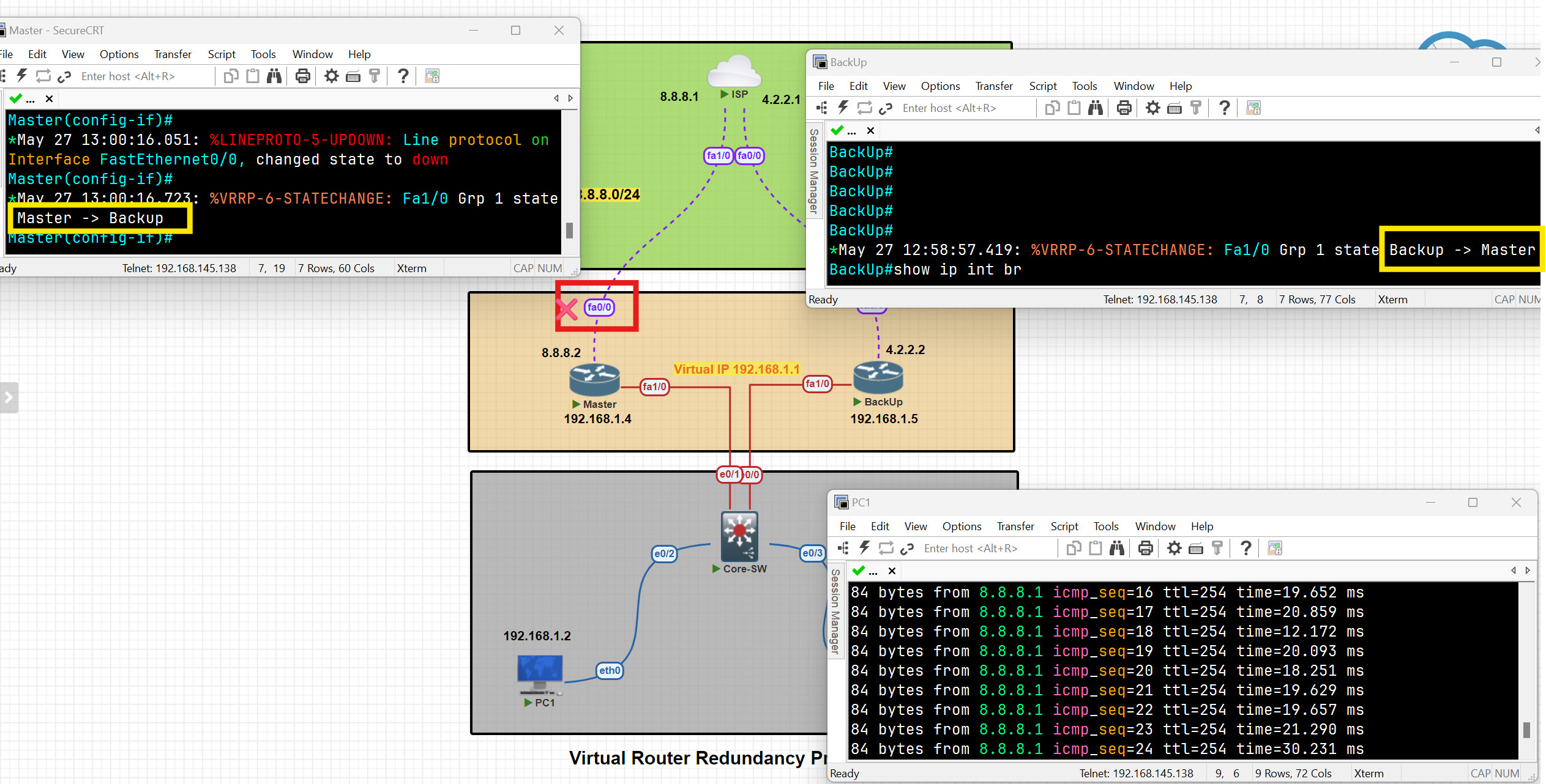
As you can see, after the shutdown of interface Fa0/0, the traffic switched from the master to the backup, and the state of the routes changed.
When the status of the tracked interface changed to 'up,' the traffic and states of the switches reverted to their previous status.
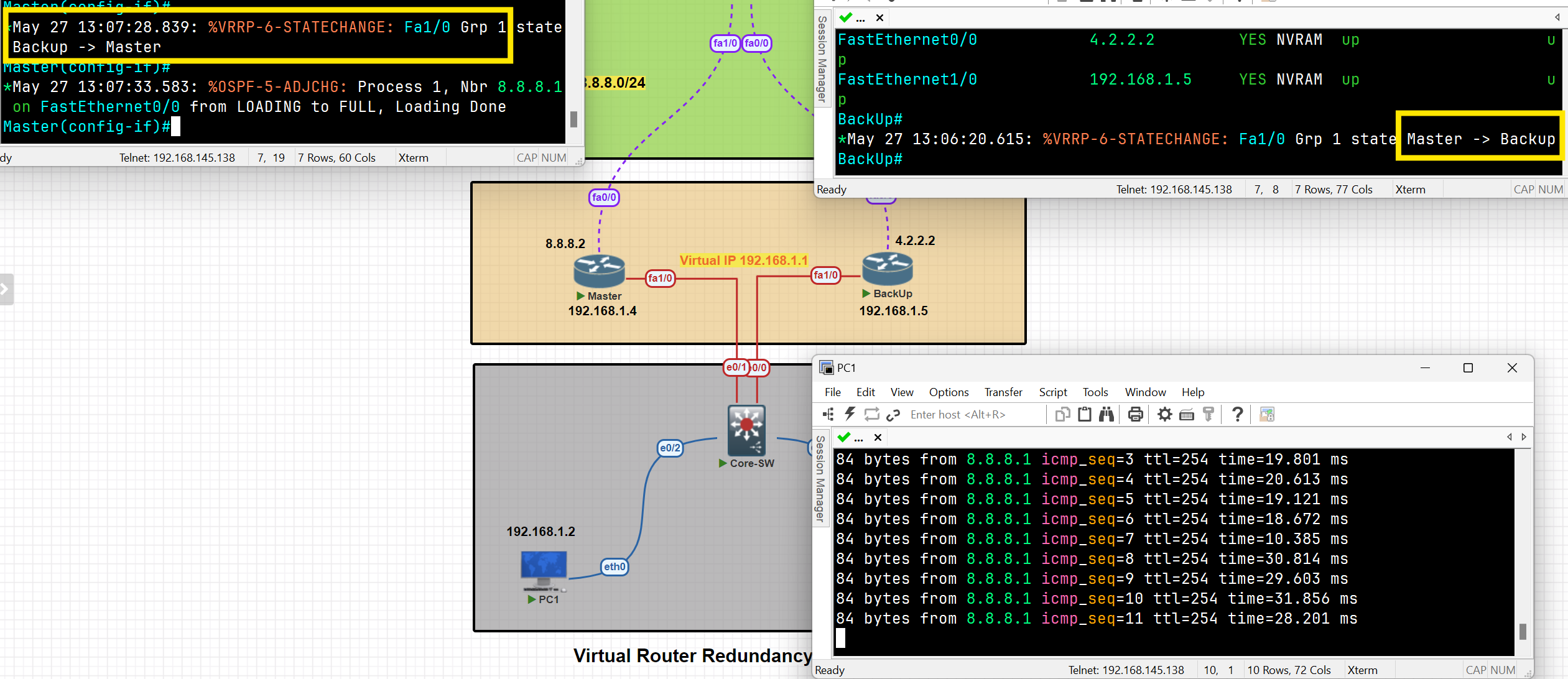
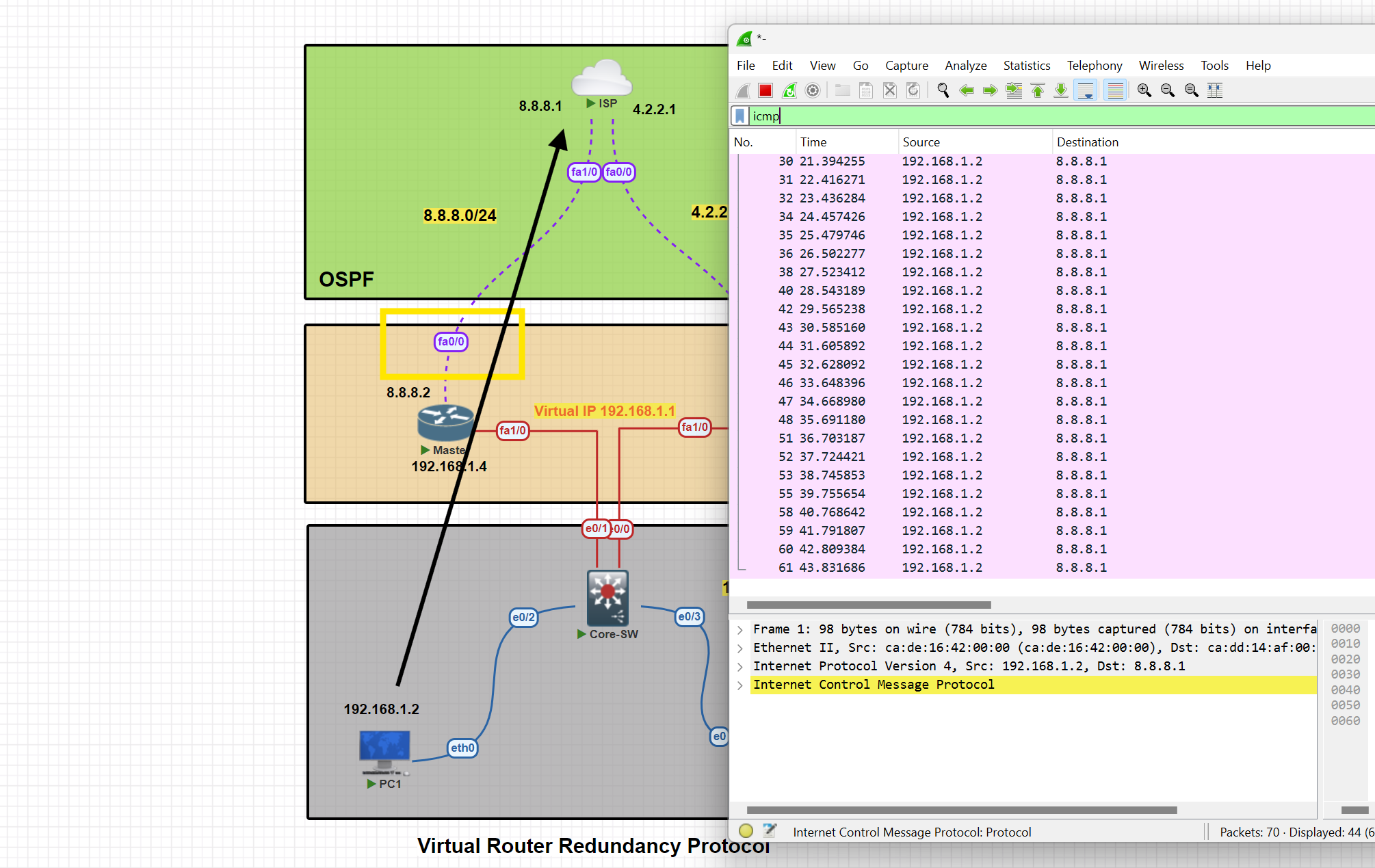
HSRP
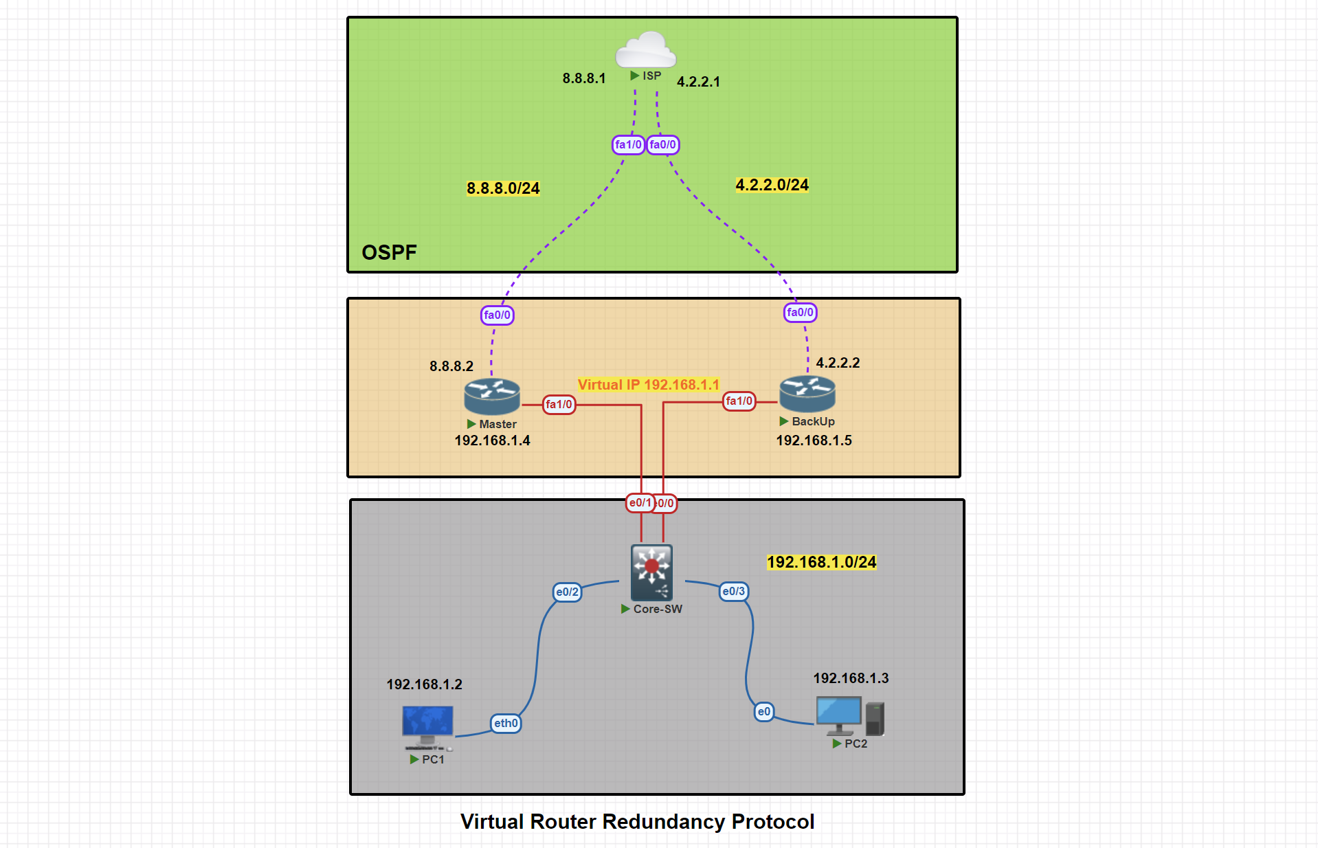
In this scenario, two routers are connected to the ISP. We will proceed with configuring VRRP, designating one router as the Active and the other as the backup.
Basic IP Configuration
PC1> ip 192.168.1.2 255.255.255.0 192.168.1.1
Active#conf t
Active(config)#
Active(config)#int fa 1/0
Active(config-if)#ip address 192.168.1.4 255.255.255.0
Active(config-if)#no shut
Active(config-if)#exit

Active(config)#int fa0/0
Active(config-if)#ip address 8.8.8.2 255.255.255.0
Active(config-if)#no shutdown
Active(config-if)#exit
Active(config)#exit
Active#wr
BackUp#conf t
StandBy(config)#int fa1/0
StandBy(config-if)#ip address 192.168.1.5 255.255.255.0
StandBy(config-if)#no shutdown
StandBy(config-if)#exit

StandBy(config)#int fa0/0
StandBy(config-if)#ip address  4.2.2.2 255.255.255.0
StandBy(config-if)#no shutdown

StandBy(config-if)#exit
StandBy(config)#exit
StandBy#wr
ISP#conf t
ISP(config)#int fa 1/0
ISP(config-if)#ip address 8.8.8.1 255.255.255.0
ISP(config-if)#no shut
ISP(config-if)#exit

ISP(config)#int fa0/0
ISP(config-if)#ip address 4.2.2.1 255.255.255.0
ISP(config-if)#no shut
ISP(config-if)#exit
ISP(config)#exit
ISP#wr
OSPF Configuration
Active#conf t

Active(config)#router ospf 1
Active(config-router)#net
Active(config-router)#network 192.168.1.0 0.0.0.255 area 0
Active(config-router)#network 8.8.8.0 0.0.0.255 area 0
Active(config-router)#passive-interface fa1/0
Active(config-router)#exit
Active(config)#exit
Active#wr
StandBy#conf t
StandBy(config)#router ospf 1
StandBy(config-router)#network 192.168.1.0 0.0.0.255 area 0
StandBy(config-router)#network 4.2.2.0 0.0.0.255 area 0
StandBy(config-router)#passive-interface fa1/0
StandBy(config-router)#exit
StandBy(config)#exit
StandBy#wr
ISP#conf t
ISP(config)#router ospf 1
ISP(config-router)#network 8.8.8.0 0.0.0.255 area 0
ISP(config-router)#network 4.2.2.0 0.0.0.255 area 0
ISP(config-router)#exit
ISP(config)#exit
ISP#wr
VRRP Active Router Configuration
Active#conf t
Active(config)#int fa1/0
Active(config-if)#standby 1 ip 192.168.1.1
Active(config-if)#standby1 priority 150
Active(config-if)#standby 1 preempt
Active(config-if)#exit
Active(config)#exit
Active#
HSRP Active Router Configuration
Active#show standby
Active#show standby brief
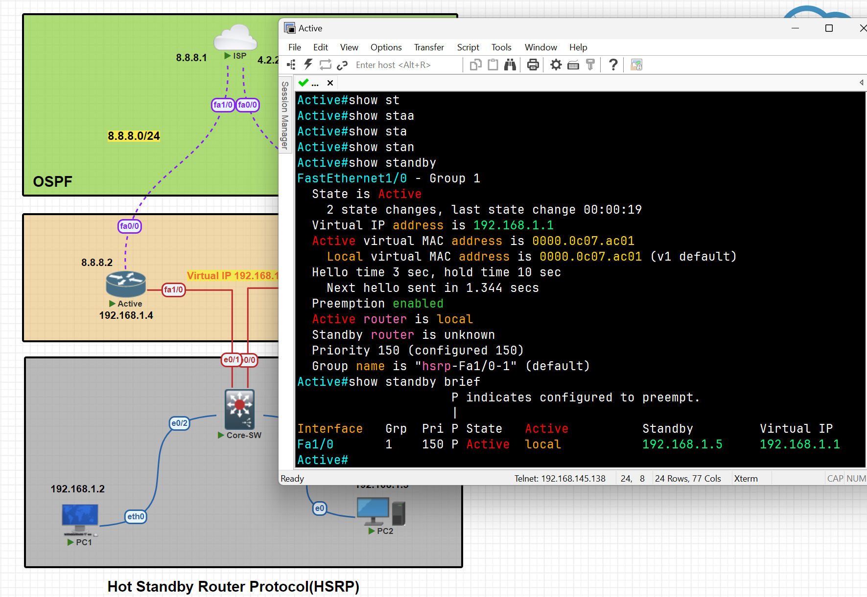
HSRP Standby Router Configuration
StandBy#conf t
StandBy(config)#int fa1/0
StandBy(config-if)#standby 1 ip 192.168.1.1
StandBy(config-if)#standby 1 preempt
StandBy(config-if)#exit
StandBy(config)#exit
StandBy#wr
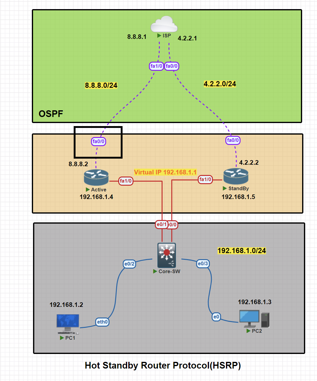
Apply Tracker to the specific interface
Active(config)#track 1 interface fa0/0 line-protocol
Mapping Tracker to the VRRP
Active(config)#int fa1/0
Active(config-if)#standby 1 track 1 decrement 60 [ decrement Priority decrement]
Testing tracker and switching traffic from Active to StandBy
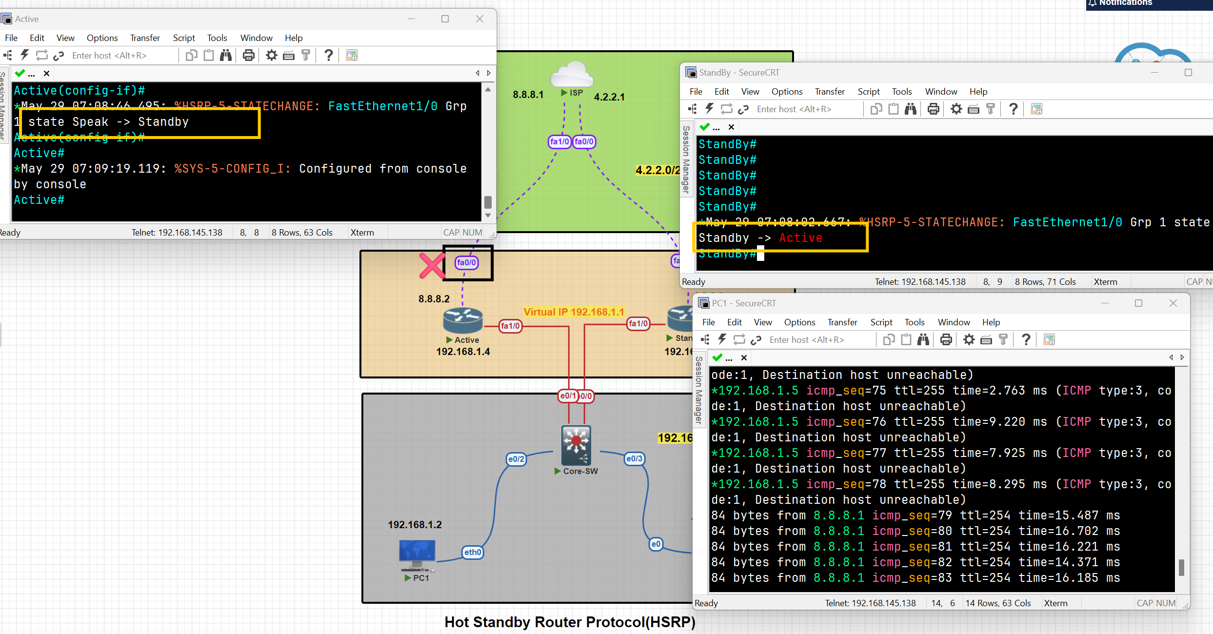
As you can see, after the shutdown of interface Fa0/0, the traffic switched from the Active to the StandBy, and the state of the routes changed.
When the status of the tracked interface changed to 'up,' the traffic and states of the switches reverted to their previous status.
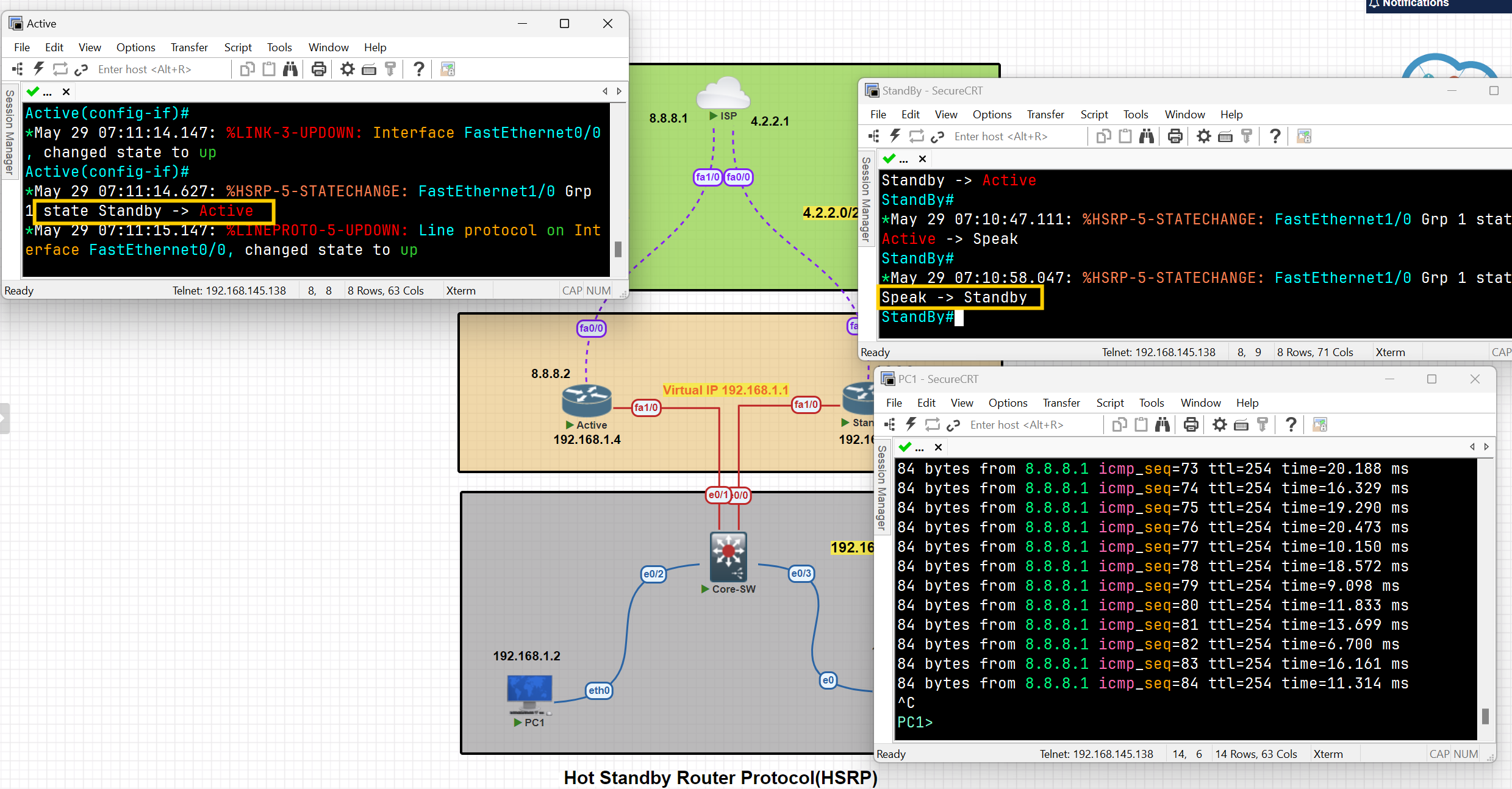
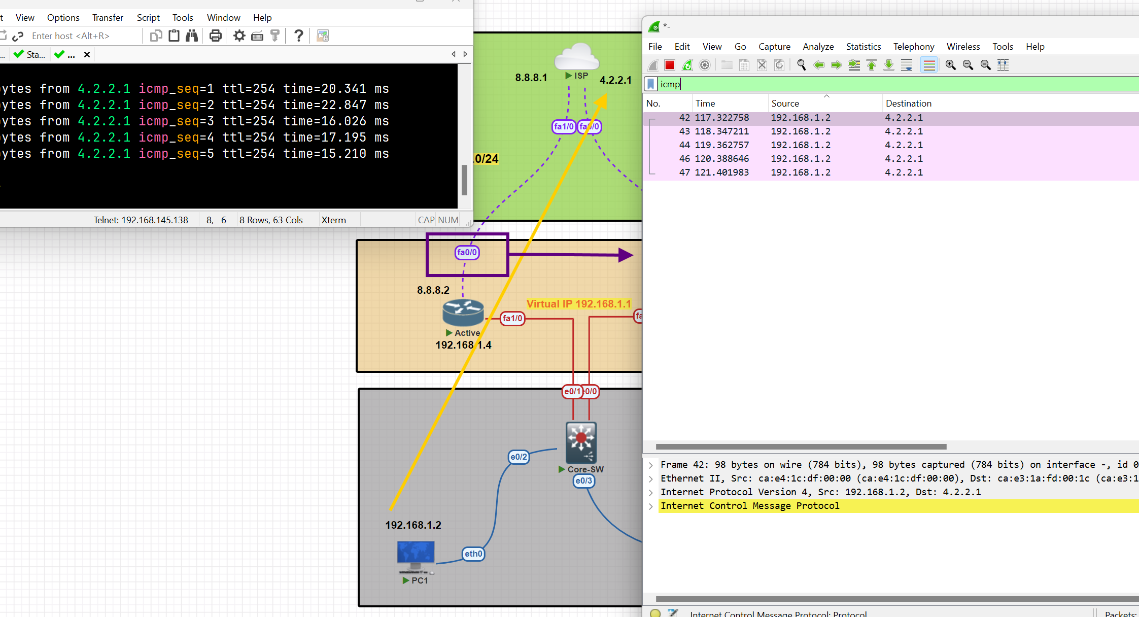
Hot Standby Router Protocol (HSRP)
💡 I tried for more than 2 days to perform this configuration, but I had an issue with both routers’ states being active. It was resolved by adding this command to the switch
Use command " no ip igmp snooping " on switch
On the active router
Router(config)#int fa 0/0
Router(config-if)#standby 1 ip 192.168.1.10
Router(config-if)#standby 1 priority 150 [ to ensure the router remain active]
On a Standby router
Router(config)#int fa 1/0
Router(config-if)#standby 1 ip 192.168.1.10
Then verify configuration
Router#show standby
Router#show arp
You can see the MAC address assigned to the virtual IP address
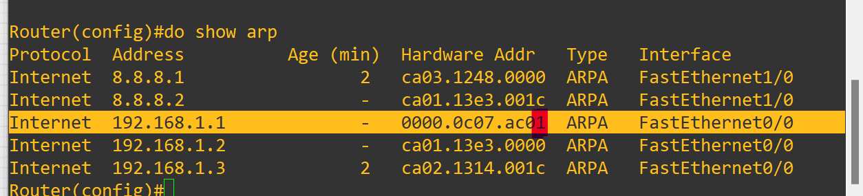
The last number of the MAC address refers to the group ID of the standby.
As you can see, after the shutdown selected interface standby starts working as an active one and forwards packets to the destination
GLBP ( Gateway Load Balancing Protocol)
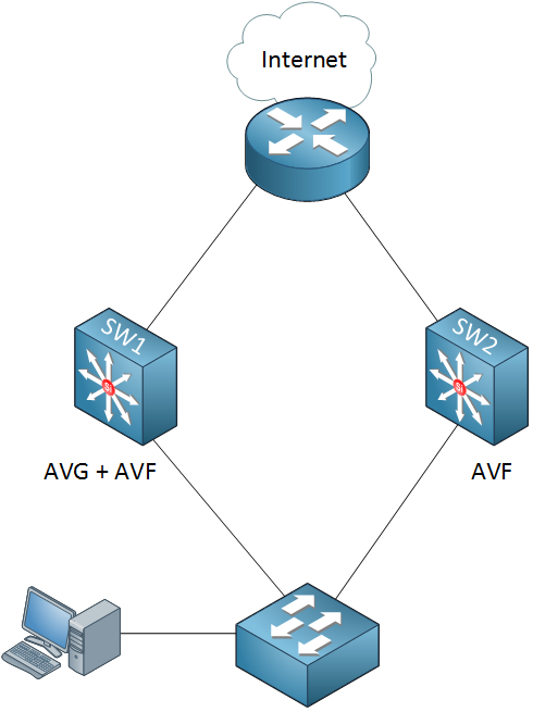
GLBP terms
Active Virtual Gateway (AVG): It is one of the routers operating GLBP in a single group which is responsible for assigning a Virtual Mac Address to all other devices running GLBP and for responding to the ARP request coming from the devices, The AVG has the highest priority value or IP addresses in the group.
Active Virtual Forwarder (AVF): Responsible for forwarding data after they are assigned by the AVG for the task. In case AVG goes down, one of the AVFs can become the AVG.
Preempt: It is a state in which one of the AVFs will become the AVG router (when the AVG router goes down). Also, when the AVG router comes up again, it will become the AVG router as its priority is still higher.
Object Tracking: GLBP uses a weighting scheme to determine the forwarding capacity of each router in the GLBP group. GLBP tracks the interface and adjusts its weighting i.e if the tracked interface goes down, then it reduces by a certain value (according to the configuration).
Load Balancing Methods:
- Round Robin: AVG will assign the virtual Mac addresses serial-wise, like the first virtual Mac address is assigned to AVF1, then to AVF2, etc. (Used By Default)
- Host-Dependent: A Host can use the same Virtual Mac Address of an AVF as long as it is reachable.
- Weighted: If you want some AVFs to forward more traffic than others you can assign them a different weight. (For example, we have 2 routers one of the routers has a higher performance than the other one, and you can use weighted to send most of the traffic to the high-performance router.)
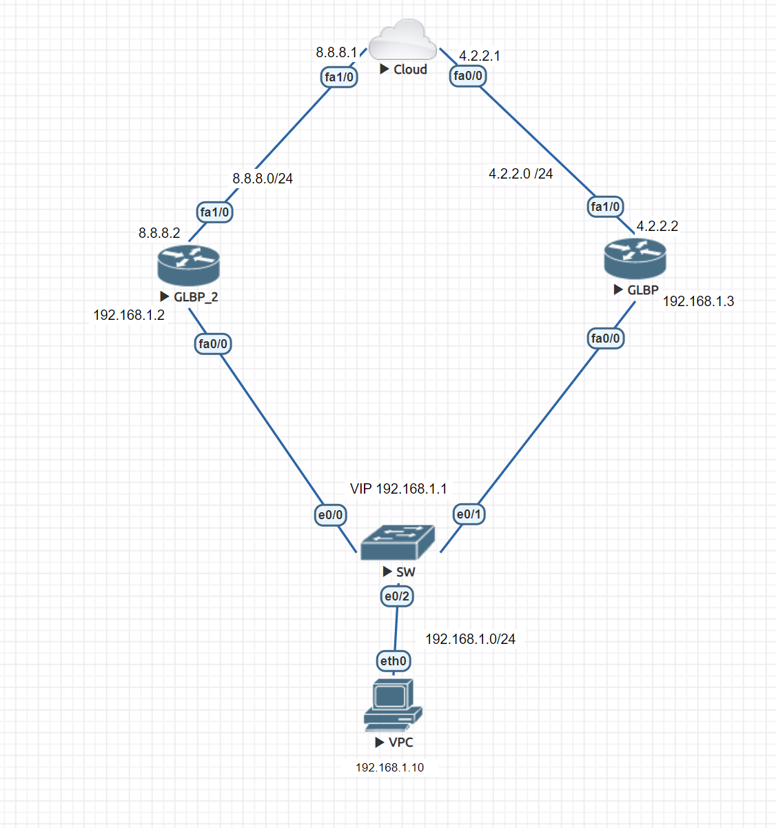
In this lab, we will configure GLBP on both routers, making GLBP_2 an active router.
GLBP Router:
Router(config)#in fa 0/0
Router(config-if)#glbp 1 (id) ip 192.168.1.1
GLBP_2 Router:
Router(config)#in fa 0/0
Router(config-if)#glbp 1 ip 192.168.1.1
Router(config-if)#glbp 1 preempt
Router(config-if)#glbp 1 priority 140
GLBP_2 is now active and can be returned to the active state if it goes down.
Now to verify and check the configuration:
Router#show glbp
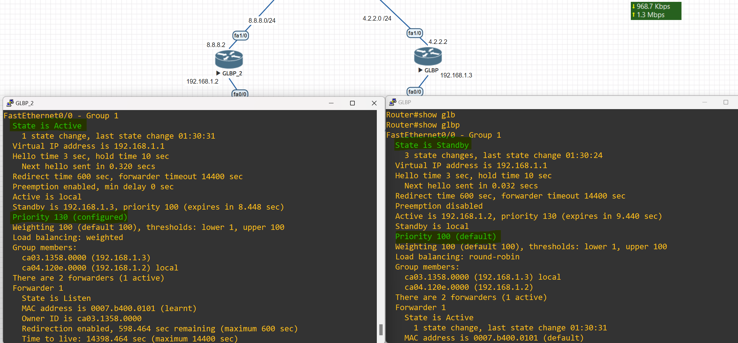
Router#show glbp brief
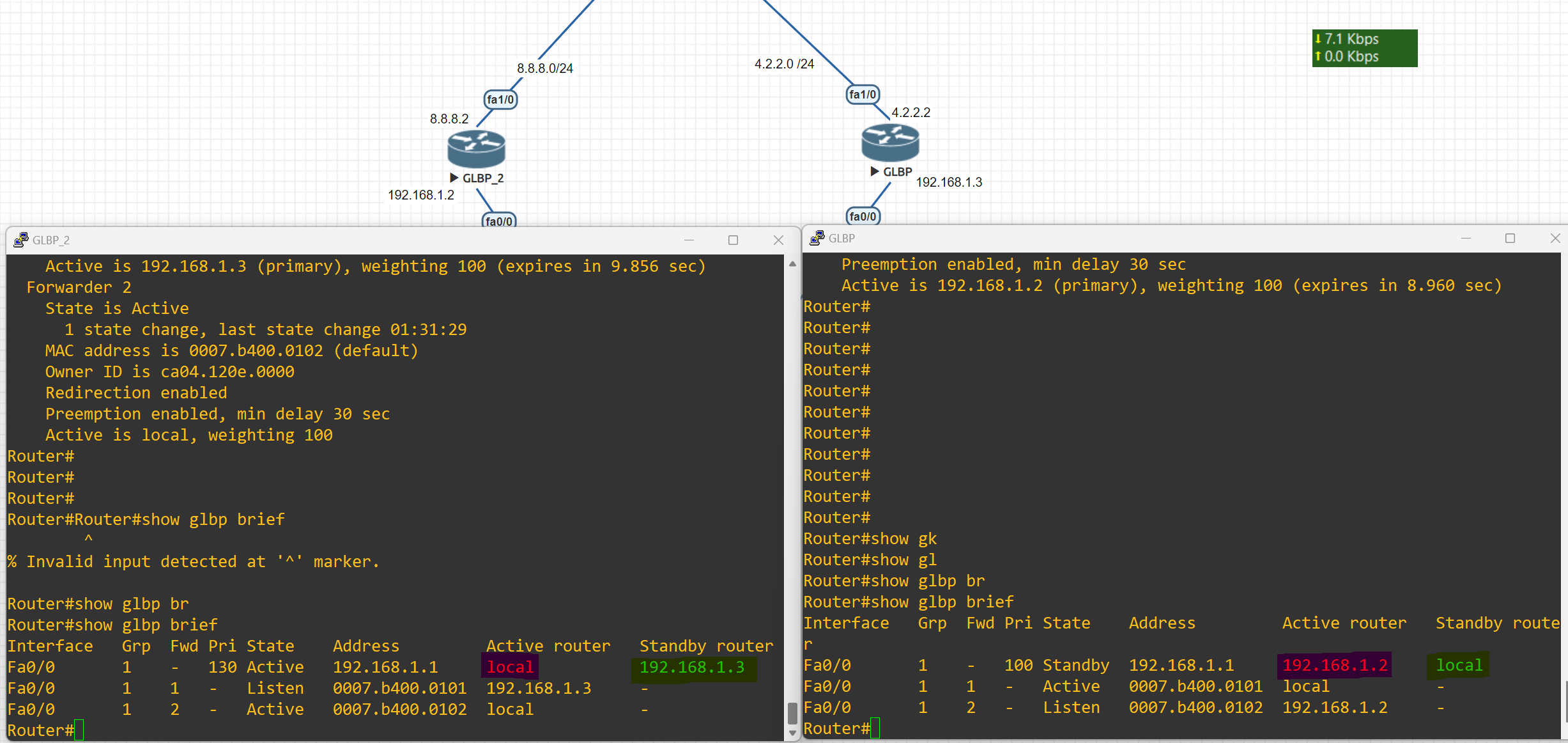
Changing Load Balancing Type
Router(config-if)#glbp 1 load-balancing weighted
host-dependent Load balance equally, source MAC determines the forwarder choice round-robin Load balance equally using each forwarder in turn weighted Load balance in proportion to forwarder weighting
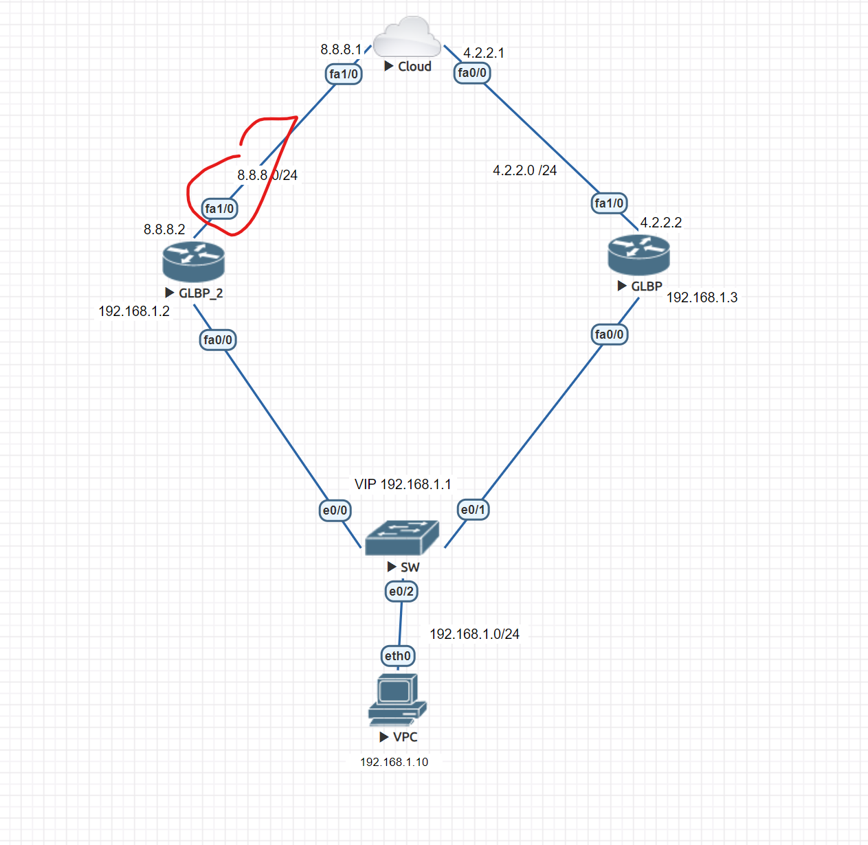
First, change the load balancing type on both routers
Router(config-if)#glbp 1 load-balancing weighted
Router(config)#int fa 0/0
Router(config-if)#glbp 1 weighting 100 lower 50 upper 95
#Configuring the weighting threshold; this command sets the default weight value, and if the value which is tracked by the weighting track be less than the lower-threshold, it will lose AVF state, and if it becomes more than the upper-threshold it will change to AVF state. This can also be configured on the interfaces that we want to act as an AVF, and not only for AVG. glbp x weighting 200 lower 150 upper 180
Then, on the router, we want to add a track and apply this command
Router(config)#track 1 interface fastEthernet 1/0 line-protocol
Router(config)#int fa 0/0
Router(config-if)#glbp 1 weighting track 1 decrement 30 (Enter the value of the decrement)
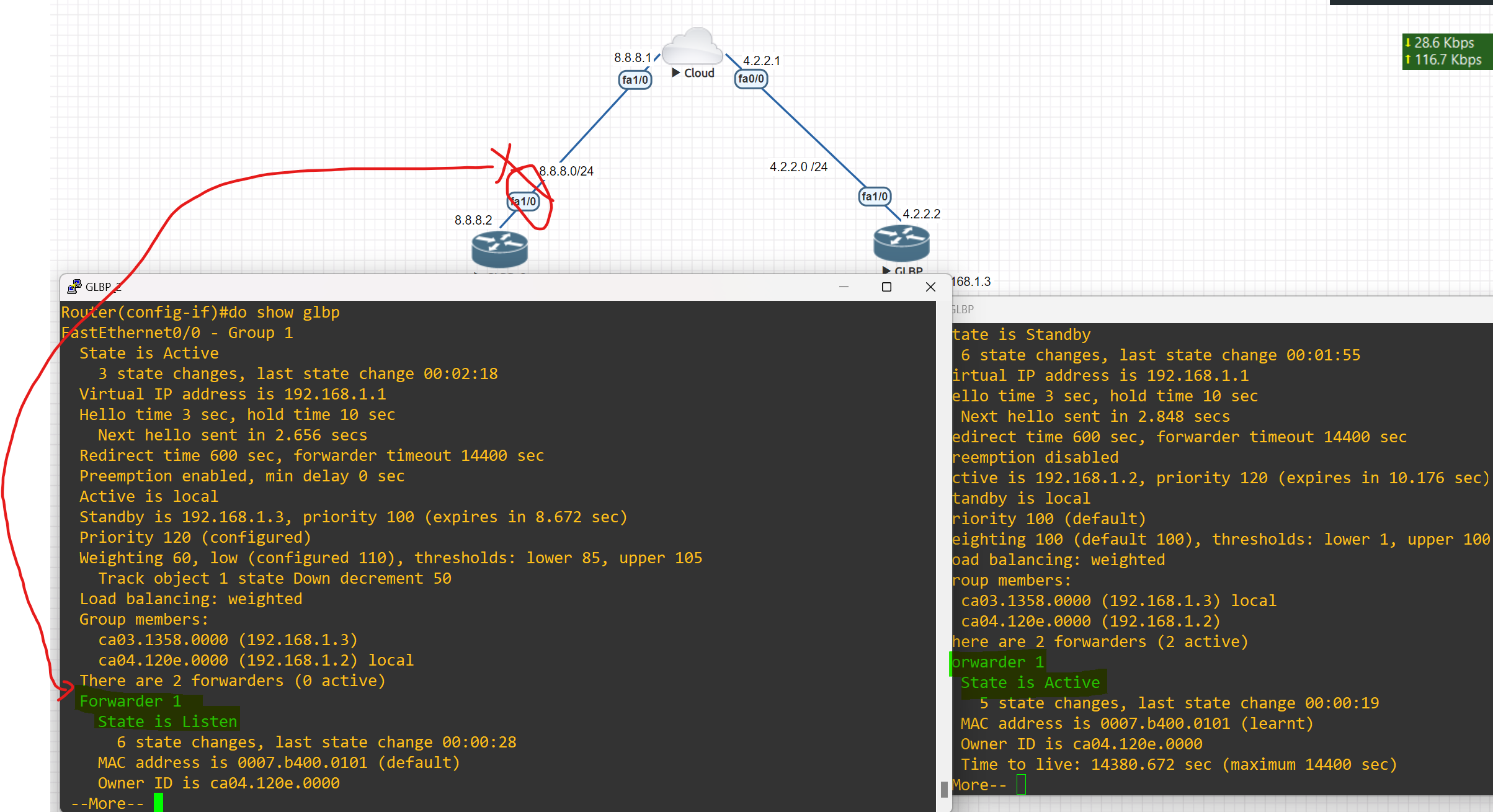
As you can see, when the tracked interface goes down, another router from beside my router starts forwarding packets.
VPN
A virtual private network, or VPN, is an encrypted connection over the internet from a device to a network. the encrypted connection helps ensure that sensitive data is safely transmitted. it prevents unauthorized people from eavesdropping on the traffic and allows users to conduct work remotely
Using a VPN will cost you nothing as it is completely free since most organizations have firewalls already installed with a built-in VPN feature. VPN also provides security for all the traffic that is sent outside your network through VPN tunnels. Lastly, VPN is scalable in that you can add unlimited tunnels and users.
VPN Benefits
- Cost saving: Eliminate the need for expensive dedicated WAN links.
- Security: use advanced encryption and authentication protocols that protect data from unauthorized access.
- Scalability: can add a large amount of capacity without adding significant infrastructure.
- Compatibility with broadband technology: supported by broadband service providers, so mobile workers and telecommuters can take advantage of their home high-speed Internet service to access their corporate networks
Type of VPN
## Remote Access (TLS)
Remote Access VPN permits a user to connect to a private network and access all its services and resources remotely. The connection between the user and the private network occurs through the internet and the connection is secure and private, Remote Access VPN is useful for home users and business users both. (which mostly used for staff to access the company network through the Internet)
Example: An employee in Baghdad logs into the company network from a laptop using VPN.
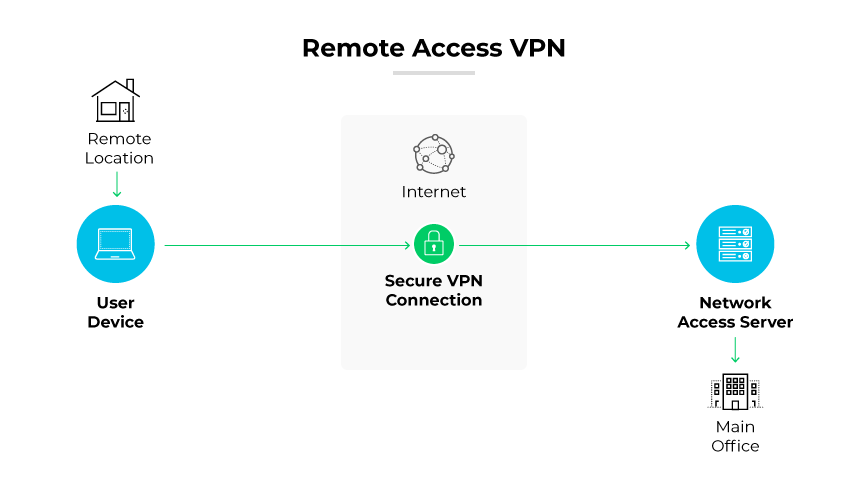
Site-to-Site VPN (IPsec)
A Site-to-Site is also called a Router-to-Router VPN and is commonly used in large companies or organizations, with branch offices in different locations, to connect the network of one office location to the network at another office location.
Example: A company’s London office and Erbil branch share resources over a VPN.
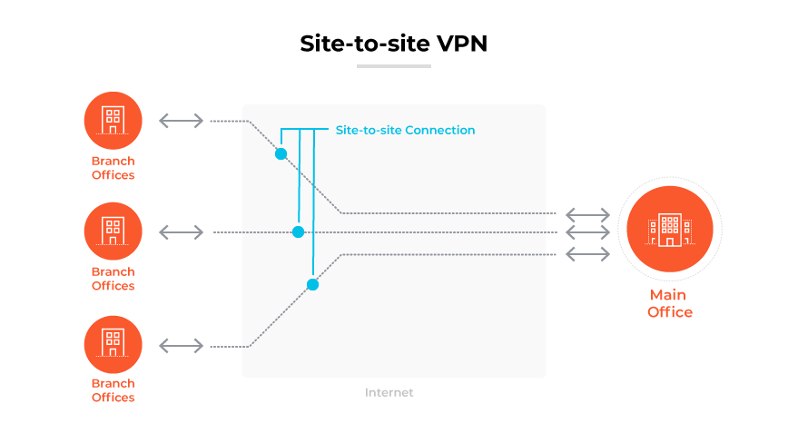
- In a site-to-site VPN, a tunnel is formed only between two tunnel endpoints (for example, the two routers connected to the Internet).
- All other devices in each site don’t need to create a VPN for themselves. They can send unencrypted data to their site’s router, which will encrypt it and forward it in the tunnel as described above.
There are two ways to implement site-to-site VPN:
Intranet VPN: it provides secured site-to-site connectivity within the company or internally.
Extranet VPN: it provides secured site-to-site connectivity outside the company. for example, customers or partners can securely access the shared resources of the company.
💡 IPsec doesn’t support broadcast and multicast traffic, only unicast. This means that routing protocols such as OSPF can’t be used over the tunnels, because they rely on multicast traffic. (This can be solved with GRE over IPsec)
SSL VPN
SSL VPN (Secure Sockets Layer Virtual Private Network): is a type of VPN that uses the SSL protocol to secure the connection between the user and the VPN server. It allows remote users to securely access a private network by establishing an encrypted tunnel between the user’s device and the VPN server. SSL VPNs are typically accessed through a web browser.
Cloud VPN
Cloud VPN, sometimes referred to as hosted VPN or VPN as a service (VPNaaS), is a VPN approach tailored for cloud environments. This VPN allows users to securely access a business's resources, data, and applications in the cloud through a web interface or a dedicated app on a desktop or mobile.
VPN Terminology
- Encryption
- Hashing
- ISAKMP
- IPSec (VPN Protocol)
- IKE
- ESP
Encryption
Encryption is a way of scrambling data so that only authorized parties understand the information.
What are the different types of Encryption?
| Symmetric Encryption | Asymmetric Encryption |
| Uses a single key to encrypt and decrypt data | Uses a public key to encrypt data and a private key to decrypt data |
| Faster encryption process | Slower encryption process |
| Example key sizes are 128 or 256-bit long | Example key sizes are 2048-bit or longer |
| Doesn’t use a lot of resources | Uses more resources |
| Cipher text is smaller, or the same size as the original plain text | Cipher text is larger or the same size as the original cipher text |
| Both symmetric and asymmetric algorithms provide authentication capability | Both symmetric and asymmetric algorithms provide authentication capability. Only non-repudiation can be achieved using an asymmetric algorithm. |
| Example algorithms are AES, DES, 3DES, IDEA and Blowfish | Example algorithms are RSA, ECC, DSA and El Gamal algorithms |
| Better at handling and transferring large amounts of data | Better at handling and transferring smaller amounts of data |
| Has the risk of someone stealing the key if it is not managed properly | Has the risk of losing the private key (the keypair is irrevocable) |
Hashing the
Hashing is a process that transforms your data into a random fixed-length value, using a hash function. For example, a piece of plain text (a password, for example) can be turned into a hashed value, making it very hard to decipher. Some common hashing algorithms include MD5, SHA-1, SHA-2, NTLM, and LANMAN.
ISAKMP
ISAKMP Internet Security Association and Key Management Protocol(ISKAMP) is like the “negotiator” in VPNs.
It helps two devices agree on how to build a secure connection (like a VPN tunnel) by handling:
- 🔐 Authentication – making sure both sides are who they say they are
- 🗝️ Key Exchange – safely sharing encryption keys
- 📋 Security Policy Agreement – agreeing on which encryption and hash methods to use
Types of Virtual Private Network (VPN) Protocols:
- Internet Protocol Security (IPsec): Internet Protocol Security, Known as IPsec, is used to secure internet communication across an IP network. IPsec secures Internet Protocol communication by verifying the session and encrypting each packet of data during the connection.
- Layer 2 Tunneling Protocol(L2TP): is a tunneling protocol that is often combined with another VPN security protocol like IPsec to establish a highly secure VPN connection. L2TP generates a tunnel between two L2TP connection points and IPsec encrypts the data and maintains secure communication between the tunnel.
- Point-to-Point Tunneling Protocol(PPTP): an old VPN protocol that uses PPP and GRE, is insecure and should not be used anymore.
- Secure Socket Tunneling Protocol (SSTP): A VPN protocol developed by Microsoft for Windows users that uses SSL to secure to secure the connection.
- IKEv2(Internet Key Exchange): is often used in combination with IPsec, IKE2 creates a secure tunnel connecting the user to the VPN server, While IPsec provides encryption and authentication.
💡 IKE is a part of IPsec, A suite of protocols and algorithms used to secure sensitive data transmitted across networks, The Internet Engineering Task Force (IETS) developed IPsec to provide security through authentication and encryption of IP Network packets and secure VPNs**.**
- OpenVPN: An open-source VPN protocol that is highly configurable and secure, OpenVPN is a widely compatible protocol that offers multiple different configuration options.
- WireGurad: A relatively new and lightweight VPN protocol that aims to be faster, simpler, and more secure than existing VPN protocols.
- GRE (Generic Routing Encapsulation): is a computer networking tunneling technology that is used to encapsulate one protocol inside another. It is not a security protocol like IPSEC but rather a versatile protocol for establishing a virtual point-to-point connection between two networks.
💡 GRE is a tunneling protocol that is used to transport multicast, broadcast, and non-IP packets like IPX, etc. IPSec is an encryption protocol. IPSec can only transport unicast packets not multicast & broadcast. Hence we wrap it GRE first and then into IPSec which is called GRE over IPSec.
| Protocal | Security | Speed | Popularity |
| OpenVPN | Very strong | Fast | Very high |
| WireGuard | Very strong | Very fast | Growing |
| IKEv2 | Strong | Very fast | High |
| L2TP | Strong | Slow | Low |
| PPTP | Weak | Very fast | Low |
| SSTP | Strong | Fast | Low |
Encapsulating Security Protocol (ESP): ESP encrypts the IP header and the payload for each packet — unless transport mode is used, in which case it only encrypts the payload. ESP adds its own header and a trailer to each data packet
VPN Implementation
Site-to-Site VPN Implementation
- Create an Access List.
- Configure ISAKMP policy. Phase 1
- IPSec Transform Set, phase 2
- Create crypto MAP. (connecting the tunnels created in Phase 1 and Phase 2).
- Apply a cryptographic map on the interface. (exit interface)
IPsec VPN negotiation occurs in two phases. In Phase 1, participants establish a secure channel in which to negotiate the IPsec security association (SA). In Phase 2, participants negotiate the IPsec SA for authenticating traffic that will flow through the tunnel.
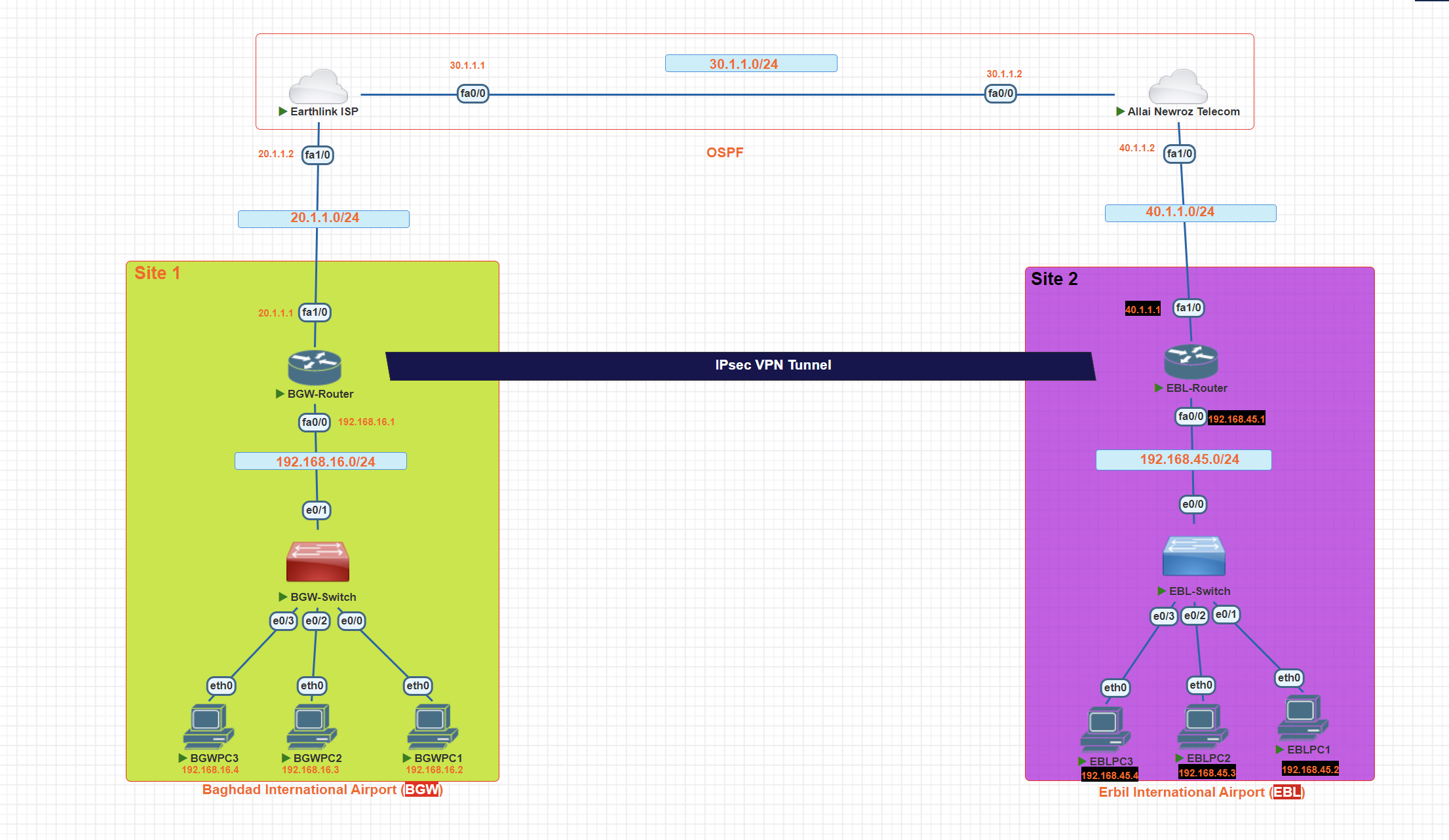
In this scenario, we will create a site-to-site VPN using IPsec between two airports in Iraq.
Step 1: Define interesting traffic
To make use of the IPsec encryption with the VPN, it is necessary to define extended access lists to tell the router which traffic to encrypt. A packet that is permitted by an access list used for defining IPsec traffic is encrypted if the IPsec session is configured correctly. A packet that is denied by the IPsec access list is not dropped. It is sent unencrypted
access-list 100 permit ip 192.168.16.0 0.0.0.255 192.168.45.0 0.0.0.255
Create the ISAKMP Policy (Phase 1)
BGW-Router(config)#crypto isakmp policy 10
BGW-Router(config-isakmp)#encryption aes 256
_**after the isakam tunnel created, then we Choose with which encryption algorithm the tunnel should be encrypted.**_
BGW-Router(config-isakmp)#authentication pre-share
_**the key will be shared.**_
BGW-Router(config-isakmp)#group 5
_**Diffie-Hellman is a protocol for creating a shared secret between two sides of a communication.**_
Verify ISAKMP policy
BGW-Router#show crypto isakmp policy
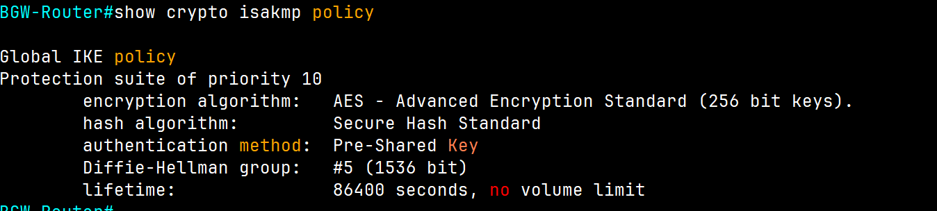
BGW-Router#show crypto isakmp sa
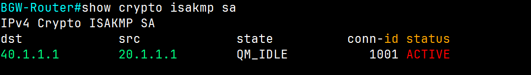
It is showing we have a tunnel with active status.
Configure pre-shared keys.
BGW-Router(config)#crypto isakmp key [Strong password] address ip ( IP address of the remote peer)
BGW-Router(config)#crypto isakmp key iqairport address 40.1.1.1
Note: There should be the same password on each side.
we told this router, we have the router from the other side and have a public IP, by using this public IP create a VPN connection.
Because pre-shared keys are used as the authentication method in the IKE policy, a key must be configured on each router that points to the other VPN endpoint. These keys must match for authentication to be successful. The global configuration mode crypto isakmp key key-string address ip-address command is used to enter a pre-shared key. Use the IP address of the remote peer, which is the remote interface that the peer would use to route traffic to the local router.
BGW-Router#show crypto isakmp key
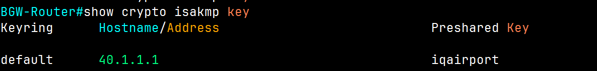
Configure IPsec (second tunnel) phase 2
BGW-Router(config)#crypto ipsec transform-set **BGW-EBL** [name] esp-aes 256[Encryption Algorithm] esp-sha-hmac [hasing algorithm]
Create and apply a crypto map
crypto map [name] [sequence-num] [type]
BGW-Router(config)# crypto map **airport-map** 10 ipsec-isakmp
BGW-Router(config-crypto-map)#set peer 40.1.1.1
_**(ip of the next router we connecting together)**_
BGW-Router(config-crypto-map)#set pfs group1
**when you use a key never reuse it again.**
BGW-Router(config-crypto-map)#set security-association lifetime seconds 3600
_**every one hour the key will be changed**_
BGW-Router(config-crypto-map)#set transform-set BGW-EBL **[name of IPSec]**
BGW-Router(config-crypto-map)match address 100 (Access list number we defined in the first step)
_**which IP addresses have permission to use the created tunnel.**_
Now we have two tunnels, and we create a connection between them through a crypto map.
perfect forward secrecy (PFS) when requesting new security associations for this crypto map entry, or that IPSec requires PFS when receiving requests for new security associations, use the set pfs crypto map configuration command
BGW-Router#show crypto map
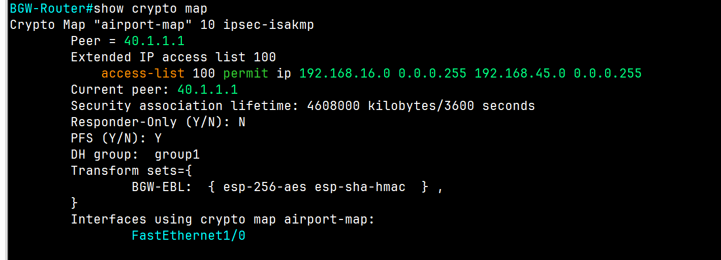
Apply the crypto map to the exiting interface
BGW-Router#conf t
BGW-Router(config)#int FastEthernet1/0
BGW-Router(config-if)#
BGW-Router(config-if)#crypto map **airport-map**
*Mar 28 11:25:39.315: %CRYPTO-6-ISAKMP_ON_OFF: ISAKMP is ON
💡 The same configuration will be applied to the router on the other side.
Verification
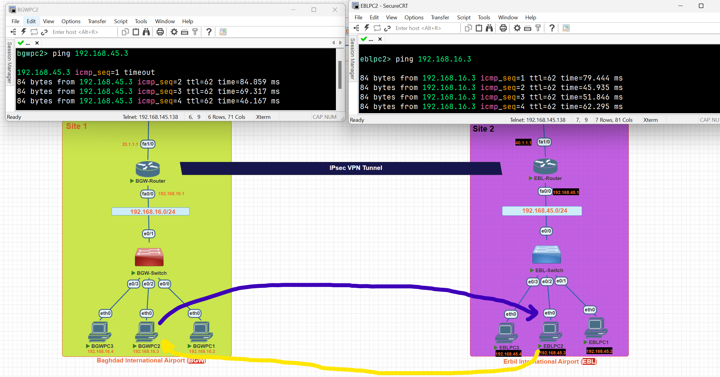
BGW-Router#show crypto ipsec sa
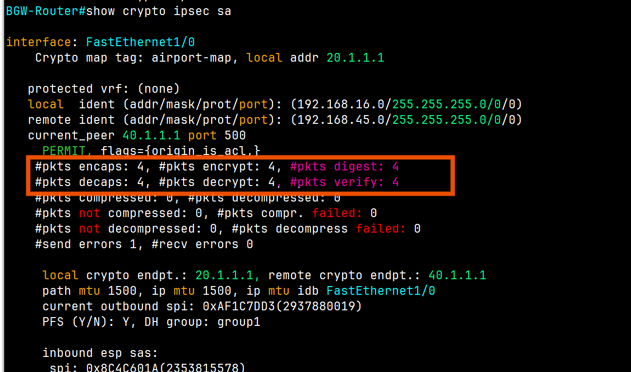
As you can see, 4 packets were encrypted and transmitted to the other airport, and 4 packets were decrypted.
Network Architectures
## LAN Architecture
- Topologies
- Network Design Layers
- PoE
WAN Architecture
- Metro Ethernet
- MPLS
- VPN
Cloud Architecture
- Virtualization and Cloud Computing
LAN Topology
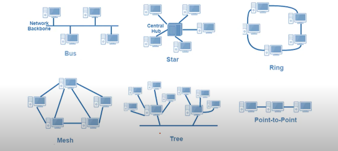
⭐ 1. Star Topology — ✅ Most Common Today
🧱 Structure:
- All devices connect to a central switch or hub.
- Think of it like a wheel: the switch is the center, devices are the spokes.
✅ Why it's most commonly used:
| Reason | Explanation |
| Easy to manage | Centralized control from the switch |
| Easy to add/remove devices | No disruption to the whole network |
| Good performance | Switch reduces collisions |
| Fault isolation | A failure in one cable/device doesn’t affect others |
Network Design
Network Design: Three-Tier Architecture
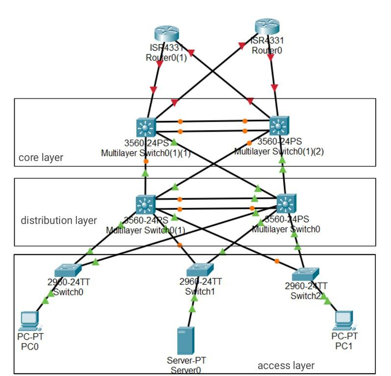
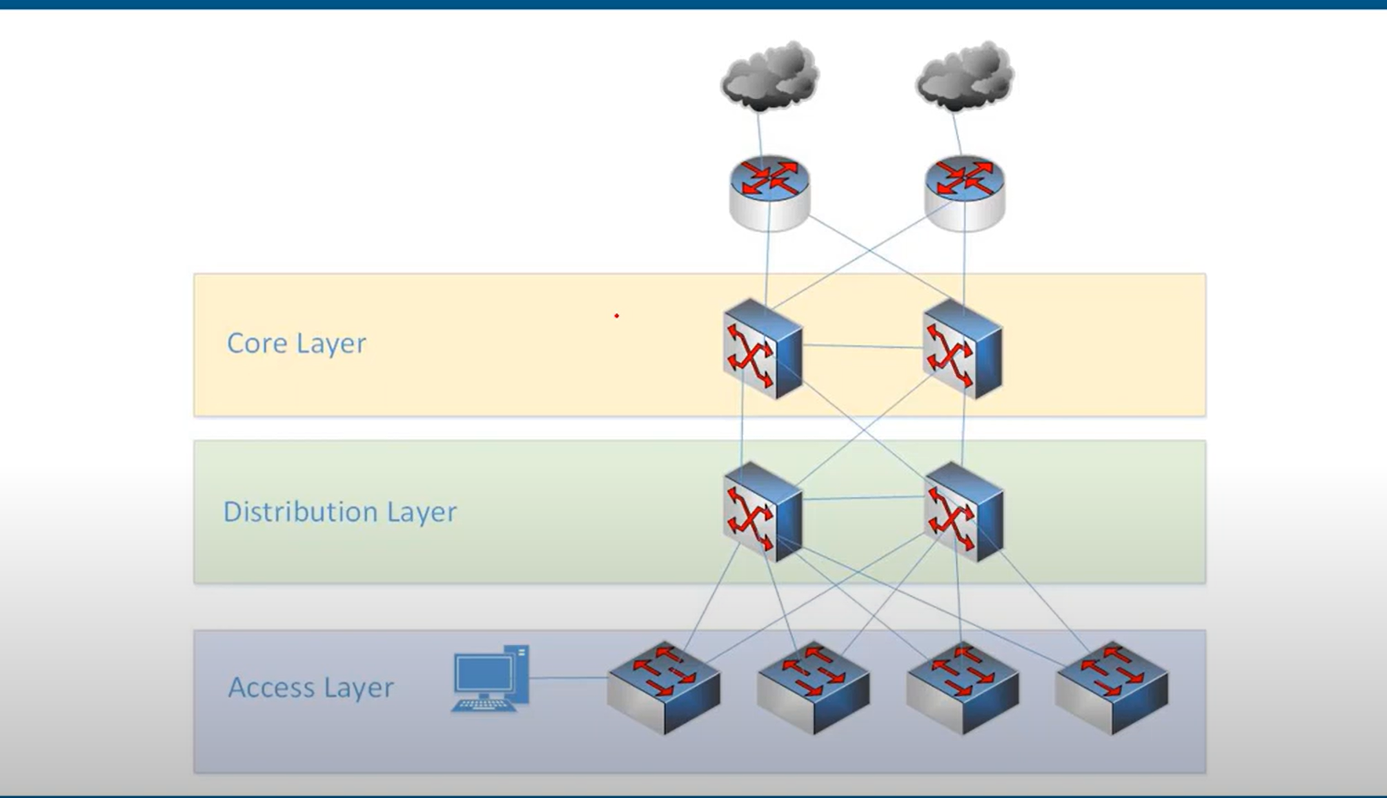
- Access layer: provides a connection point for end-user devices to the network and allows multiple hosts to connect to other hosts through a network device, usually a switch, such as the Cisco 2960-XR shown in the figure, or a wireless access point. Typically, all devices within a single access layer will have the same network portion of the IP address.
- the layer that end hosts connect to (PCs, printers, cameras, etc.)
- typically Access Layer Switches have lots of ports for end hosts to connect to
- QoS marking is typically done here
- Security services like port security, DAI, etc. are typically performed here
switchports might be PoE-enabled for wireless APs, IP phones, etc.
Distribution layer: The distribution layer in network topology serves as the communication point between the access layer and the core**, providing routing, filtering, WAN access, and determining the fastest way to handle network service requests, Distribution layer devices control the type and amount of traffic that flows from the access layer to the core layer. It typically includes routers and multilayer switches.**
Core layer: The core layer in network topology, also known as the network backbone, is responsible for quickly transporting large amounts of traffic and providing interconnectivity between distribution layer devices. It typically consists of high-speed devices like high-end routers and switches with redundant links.
Network Design Two-Tier Architecture (collapsed core)
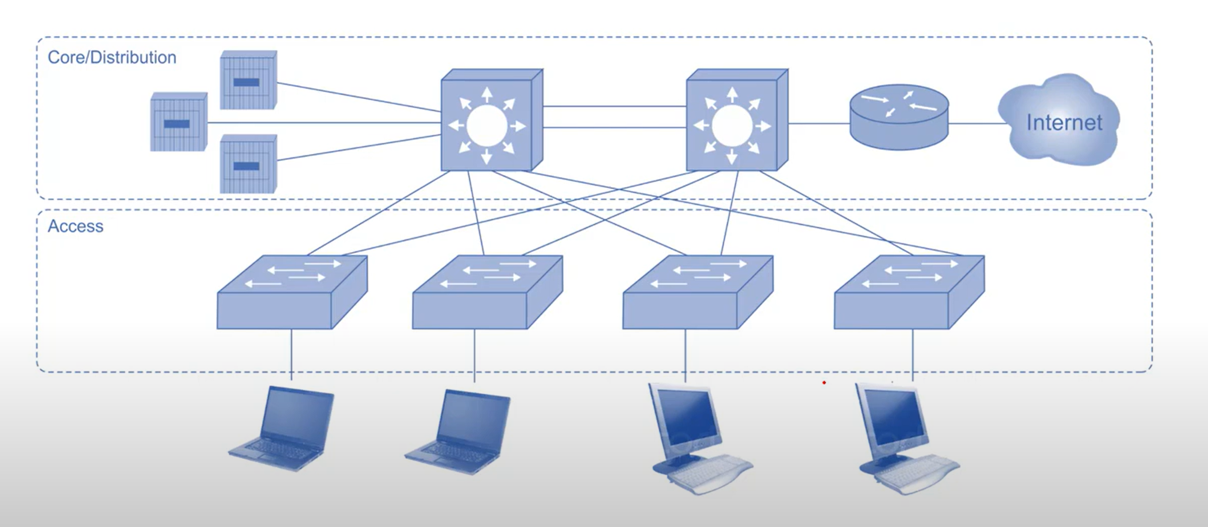
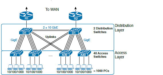
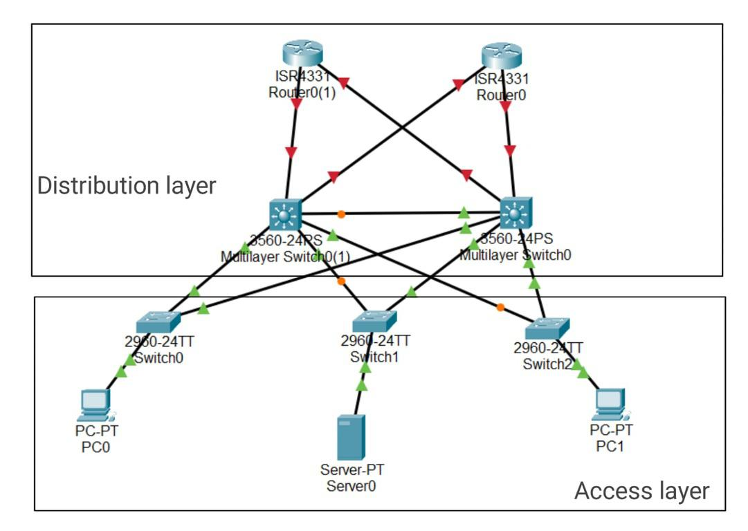
many Small enterprise networks do not grow significantly larger over time, Therefore, A two-tier hierarchical design where the core and distribution layers are collapsed into one layer is often more practical . Collapsed Core is when the distribution layer and Core layer functions are implemented by a single device.
Spine-leaf Architecture
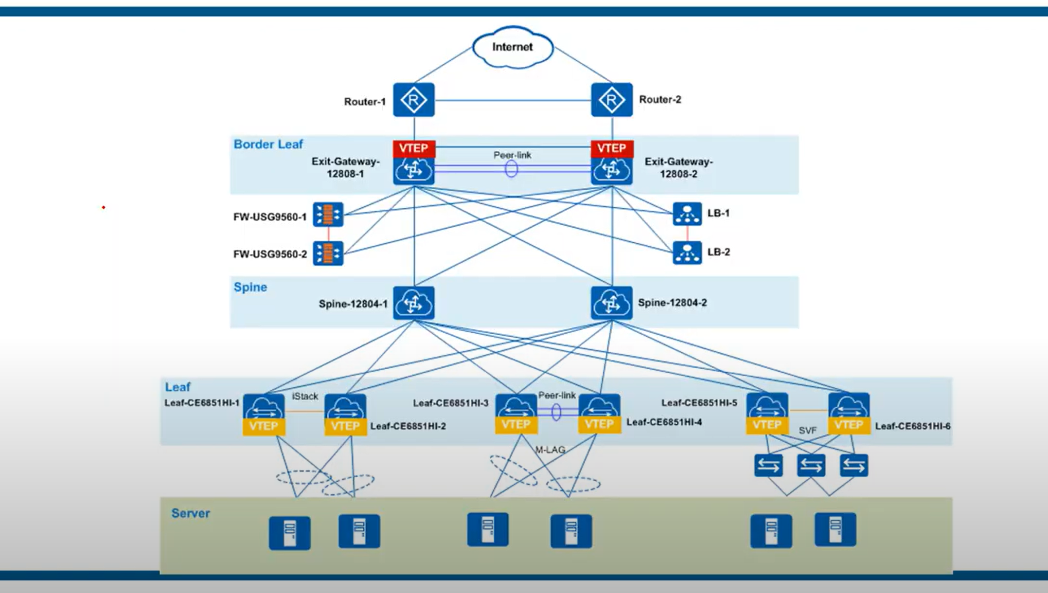
The spine-leaf architecture has become a popular data center architecture, bringing many advantages to the data center, such as scalability, network performance, etc. The benefits of spine-leaf architecture in modern networks are summarized here in three points.
Increased redundancy: The spine-leaf architecture connects the servers with the core network, and has higher flexibility in hyper-scale data centers. In this case, the leaf switch can be deployed as a bridge between the server and the core network. Each leaf switch connects to all spine switches, which creates a large non-blocking fabric, increasing the level of redundancy and reducing traffic bottlenecks.
Performance enhancement: The spine-leaf architecture can effectively avoid traffic congestion by applying protocols or techniques such as transparent interconnection of multiple links (TRILL) and shortest path bridging (SPB). The spine-leaf architecture can be Layer 2 or Layer 3, so uplinks can be added to the spine switch to expand inter-layer bandwidth and reduce oversubscription to secure network stability.
Scalability: The spine-leaf architecture has multiple links that can carry traffic. The addition of switches will improve scalability and help enterprises expand their business later.
There are some rules about Spine-Leaf architecture: → Every Leaf switch is connected to every Spine switch. → Every Spine switch is connected to every Leaf switch. → Leaf switches do not connect to other Leaf switches. → Spine switches do not connect to other Spine switches. → End hosts (servers etc.) only connect to Leaf switches.
- The path taken by traffic is randomly chosen to balance the traffic load among the Spine switches.
- Each server is separated by the same number of ‘hops’ (except those connected to the same Leaf), providing consistent latency for East-West traffic.
How to Design a Network?
- A clear map of the network
- The structure and layout of the cabling required
- The quantity, type, and location of all devices on the network.
- Your IP Addressing structure.
- Details of your network security architecture and processes.
- Budgets and Scalability.
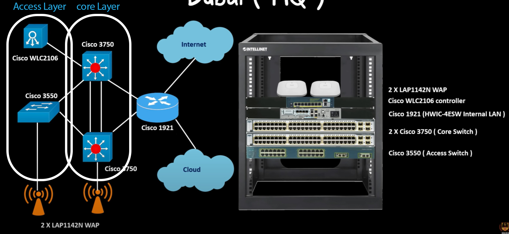
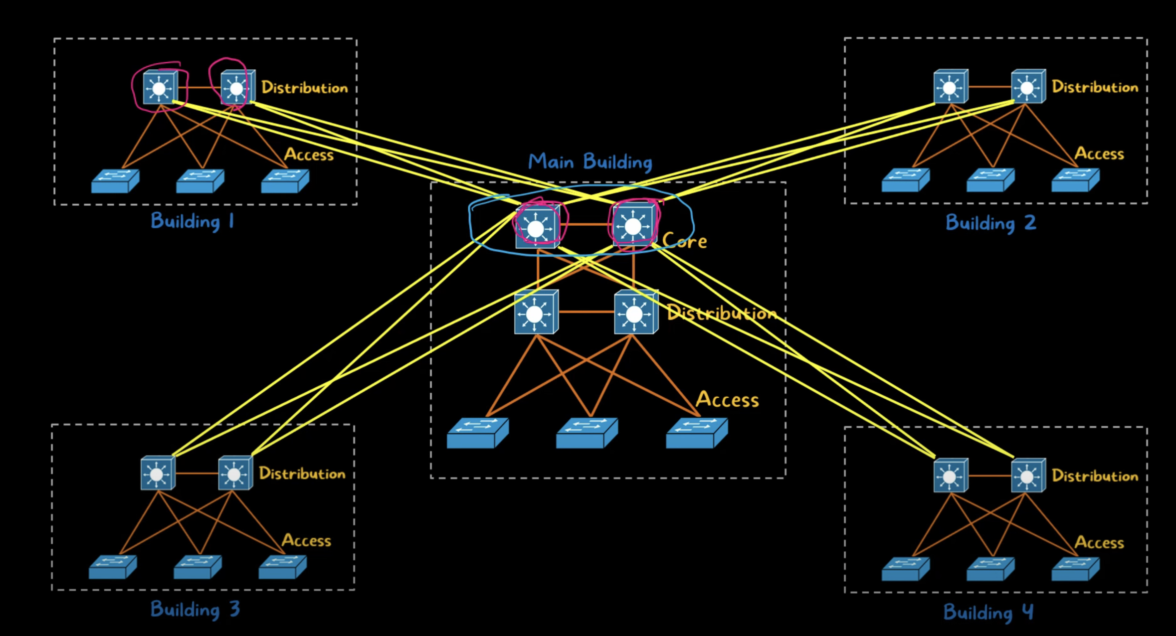
https://www.youtube.com/watch?v=srV9gKvuTC0
POE
Sending electricity over the unused Ethernet wires to power a connected device. Through inline power or using power over Ethernet (POE). Cisco IP phones, devices such as wireless access points, and video surveillance equipment can also use PoE.
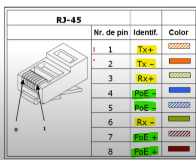
As you can see, 4 of the lines are used to receive and transmit data, and 4 other lines are used to send power.
| PoE Extender | to extend the reach of both power and data signals over Ethernet cables. (the standard 100-meter (328 feet) limit) |
| POE Injector | Connects POE-enabled network devices to a non-PoE LAN Switch port |
| POE Splitter | A small device that separates the data and power signals in a power over Ethernet(POE) cable, providing power to a non-PoE device |
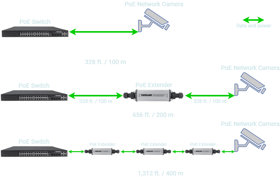
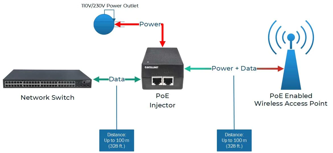
WAN Architecture
- Metro Ethernet
- MPLS
- VPN
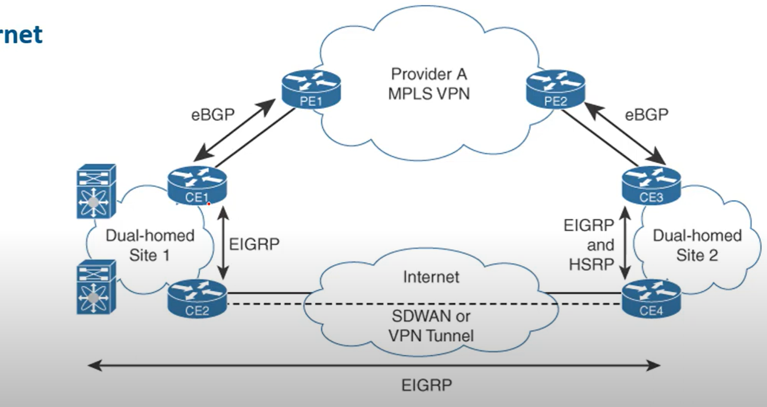
Metro Ethernet
Metro Ethernet is an Ethernet transport network that provides point-to-point or multipoint connectivity services over a metropolitan area network (MAN). Ethernet originated as a LAN technology and became a replacement for low-speed WAN technologies.
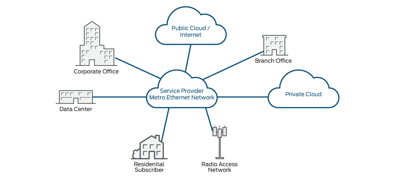
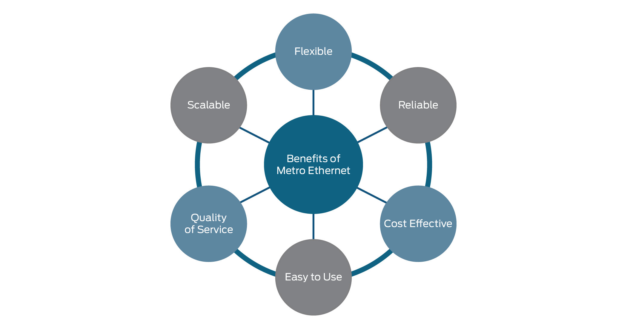
MPLS
Multiprotocol Label Switching (MPLS) is a data-forwarding technology that increases the speed and controls the flow of network traffic. With MPLS, data is directed through a path via labels instead of requiring complex lookups in a routing table at every loop.
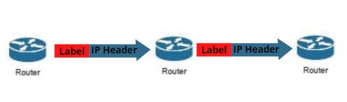
When is MPLS used?
MPLS can be used when speed and reliability are highly important. Applications that require near-immediate data delivery are known as real-time applications. Voice calls and video calls are two common examples of real-time applications.
##
What are the drawbacks of MPLS?
- Cost: MPLS is more expensive than regular internet service.
- Long Setup Time: Setting up complicated paths across one or more large networks takes time.
- Lack of encryption: MPLS is not encrypted; any attacker who intercepts packets on MPLS paths can read them in plaintext. Encryption has to be set up separately.
MPLS packets: Not encrypted by default.
Security options: VPNs for encryption, traffic isolation, and secure network infrastructure.
💡 MPLS routers work as a switch just forwarding the incoming packets, without decapsulating the packet in layer 3 to check the IP of the destination and checking the routing table.
Virtualization
Virtualization is the ability to run multiple operating systems on a single physical system and share the underlying hardware resources.
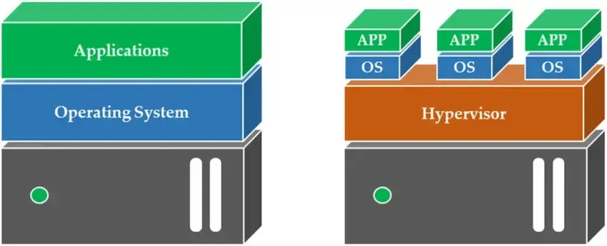
## Hypervisor
A hypervisor is software that creates and runs virtual machines (VMS). A hypervisor allows one host computer to support multiple guest VMs by virtually sharing its resources, such as memory and processing.
Two Types of Hypervisor
Type 1
Type 1, or “bare metal,” is more optimized because it is already installed and runs directly on the hardware it came included with. It replaces a host operating system, and VM resources are scheduled directly to the hardware by the hypervisor.
💡 This type of hypervisor is most common in an enterprise data center or other server-based environment.
KVM, Microsoft Hyper-V, and VMware vSphere are examples of type 1 hypervisors. KVM was merged into the Linux kernel in 2007. If you are using a modern version of Linux, you already have access to KVM
Type 2
A type 2 hypervisor is also known as a hosted hypervisor and is run on a conventional operating system as a software layer or application.
💡 A type 2 hypervisor is better for individual users who want to run multiple operating systems on a personal computer.
VMware Workstation and Oracle VirtualBox are examples of a type 2 hypervisor.
Containers vs. VMs (optional)
Containers and virtual machines are very similar resource virtualization technologies. Virtualization is the process in which a system's singular resource like RAM, CPU, Disk, or Networking, can be ‘virtualized’ and represented as multiple resources. The key differentiator between containers and virtual machines is that virtual machines virtualize an entire machine down to the hardware layers, and containers only virtualize software layers above the operating system level.
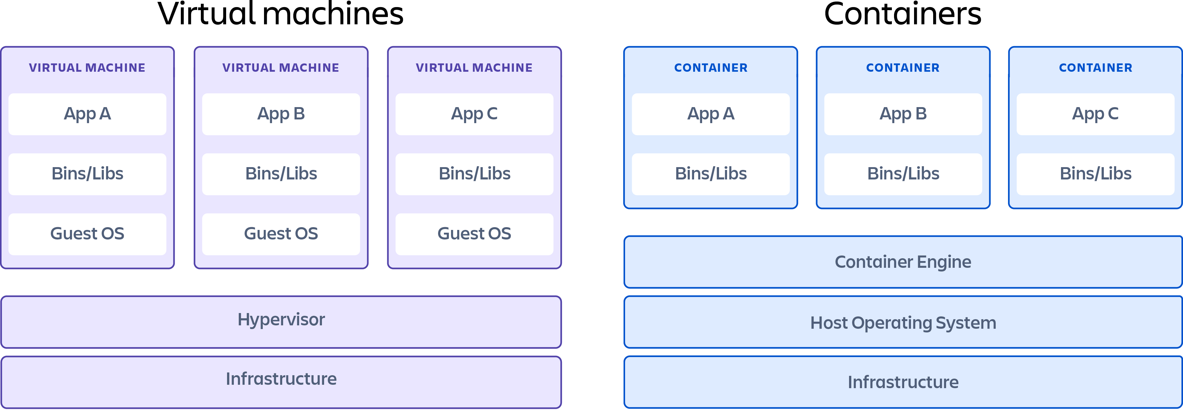
Types of Virtualization
- Application Virtualization
- Desktop Virtualization
- Hardware Virtualization
- Network virtualization (VLAN)
- Storage Virtualization
Cloud Computing
On-premise (or on-premises) refers to software, hardware, or IT infrastructure that is physically located within a company's facilities, rather than being hosted remotely (like in the cloud).
Cloud Computing
Cloud computing is a model that allows customers simple, on-demand network access to a shared pool of configurable computing resources (e.g., networks, servers, storage, applications, and services) from anywhere. These resources can be rapidly provisioned and released with minimal management effort or interaction with the service provider. This cloud model is composed of five essential characteristics, three service models, and four deployment models.
Essential Characteristics of Cloud
On-Demand self-service: Users can automatically provision computing resources like storage or processing without human interaction with the service provider.
✅ Example: Creating a virtual machine instantly through a cloud dashboard.
Broad Network Access: Cloud services are available over the network and can be accessed via standard devices such as laptops, smartphones, and tablets.
✅ Example: Accessing cloud storage like Google Drive or Dropbox from any device with internet.
Resource Pooling: Cloud providers use multi-tenant models to serve multiple customers using shared resources (like memory, storage, and bandwidth), dynamically assigned and reassigned according to demand.
✅ Example: One physical server running virtual machines for multiple clients.
Rapid Elasticity: Resources can be quickly scaled up or down, sometimes automatically, to meet demand.
✅ Example: Auto-scaling web servers during traffic spikes.
Measured service: Cloud Systems automatically control and optimize resource use by metering usage, so customers pay only for what they use.
✅ Example: Paying per gigabyte of storage or per hour of compute time.
Cloud Computing Service models
- Software as a service (SaaS): Instead of users installing an application on their device, SaaS applications are hosted on cloud servers, for example, Salesforce, Mailchimp, and Slack.
- Platform as a Service (PaaS): PaaS vendors offer everything necessary for building an application, including development tools, infrastructure, and operating systems, over the Internet. PaaS can be compared to renting all the tools and equipment necessary for building a house, instead of renting the house itself. PaaS examples include Heroku and Microsoft Azure.
- Infrastructure as a Service (IaaS): The cloud provider is responsible for giving IT managers access to the network equipment, virtualized network services, and supporting network infrastructure. Using this cloud service allows IT managers to deploy and run software code, which can include operating systems and applications. Examples include Amazon EC2 and Google Compute Engine.
Cloud Computing Deployments
Public Cloud: Cloud-based applications and services offered in a public cloud are made available to the general population. Service may be free or offered on a pay-per-use model.
Private Cloud (On-premise Cloud): Cloud-based applications and services offered in a private environment to one organization.
Hybrid cloud: deployments combine public and private clouds, and may even include on-premises legacy servers. An organization may use its private cloud for some services and its public cloud for others, or it may use the public cloud as a backup for its private cloud.
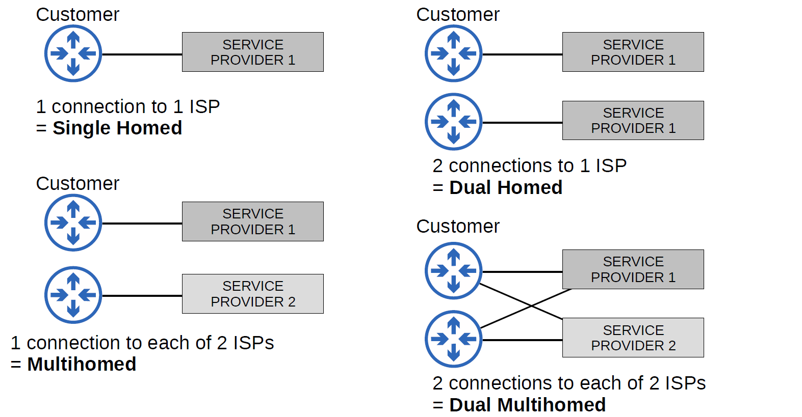
Network Automation
What is Automation?
- Network Automation is the process of automating the configuration, management, testing, deployment, and operation of physical and virtual devices within a network. With everyday network tasks and functions automated and repetitive processes controlled and managed automatically, network service availability is ensured.
Why Automation?
- Remove the risk of human error.
- Easy control of device configuration for consistency and accuracy.
- Reduces the workload for IT staff.
- Standardize processes. (Vendor free)
- Zero-touch provisioning. (without touching the router for configuration)
- fast and accurate deployment of patches and updates.
SDN
- SDN stands for Software-Defined Network, which is a networking architecture approach. It enables the control and management of the network devices using software applications. Through Software Defined Network (SDN), the networking behavior of the entire network and its devices is programmed in a centrally controlled manner through software applications using open APIs.
To understand software-defined networks, it is essential to comprehend the various planes involved in networking.
- Data Plane
- Control Plane
| CONTROL PLANE | DATA PLANE |
| Control plane refers to the all functions and processes that determine which path to use to send the packet or frame. | Data plane refers to all the functions and processes that forward packets/frames from one interface to another based on control plane logic. |
| It is responsible for building and maintaining the IP routing table and how packets should be forwarded. | It is responsible for forwarding actual IP packet and moving packets from source to destination. |
| Control plane performs its task independently. | Data plane performs its task depending on Control plane. |
| In general we can say in control plane it is learned what and how it can be done. | In general we can say in data plane the actual task is performed based on what is learned. |
| It includes Spanning Tree Protocol (STP),Address Resolution Protocol (ARP),Routing Information Protocol (RIP), Dynamic Host Configuration Protocol (DHCP) etc**.** | It includes decrementing Time To Live (TTL), recomputing IP header checksum etc**.** |
| Control plane acts as a decision maker in data forwarding. | Data plane acts as a decision implementer in data forwarding. |
| Routing is performed in the control plane. | Switching is performed in the data plane. |
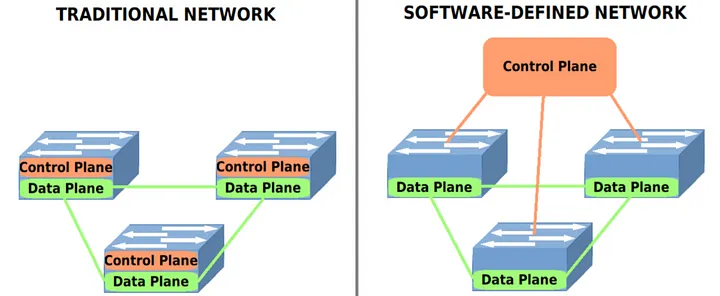
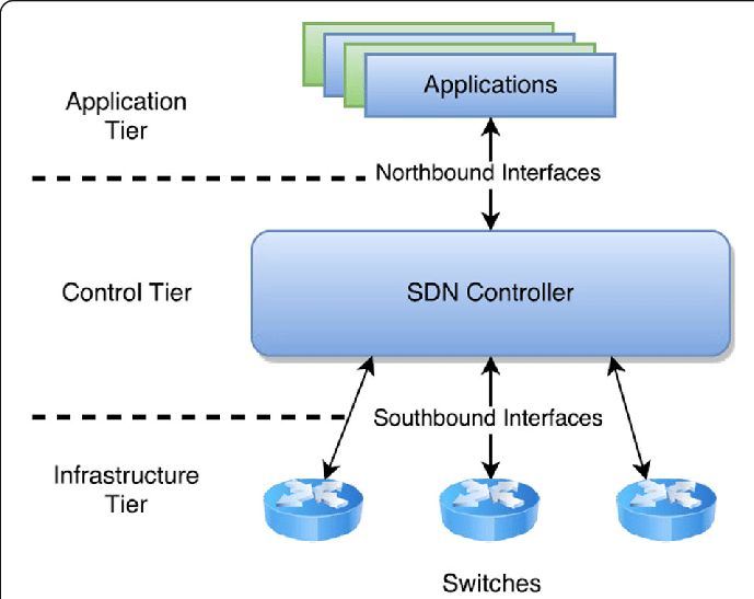
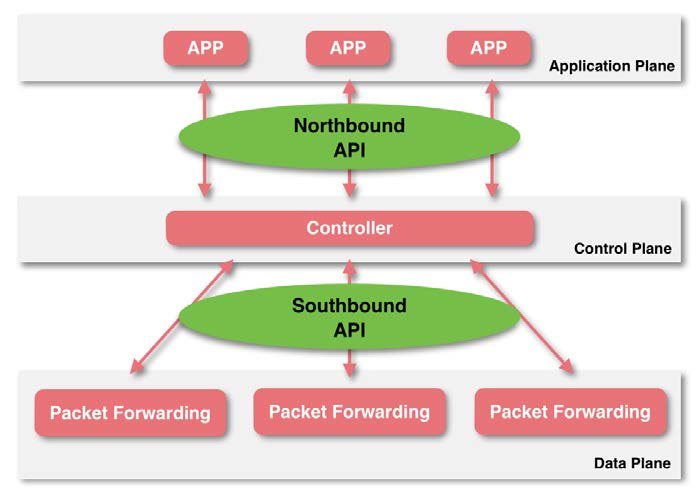
SDN Elements
- Controller: the core of an SDN architecture, which enables centralized management and control, automation, and policy enforcement across physical and virtual network environments.
- Southbound API: relay information between the controller and the individual network devices (Such as switches, access points, routers, and firewalls).
- Northbound API: relays information between the controller and the application plane.
SDN Controllers and Protocols
Protocols:
- Two of the most well-known protocols used by SDN controllers to communicate with the switches/routers are OpenFlow and Open Virtual Switch Database (OVSDB).
Controller:
- The first SDN controller was NOX.
Different Models of SDN
- Open SDN
- SDN via APIs
- SDN via Hypervisor-based Overlay network.
- Hybrid SDN.
Why SDN is Important?
- Better Network Connectivity.
- Better Deployment of Applications.
- Better Security.
- Better Control with high speed.
SDN Architecture
- Underlay is the physical or basic IP network that provides connectivity between devices (switches, routers, servers, etc.).
- Overlay is a virtual network built on top of the underlay using encapsulation technologies, such as VXLAN, OTV, VPLS, or MPLS-VPN.
- Fabric is a network topology and architecture that interconnects all devices using consistent and often automated policies. It's typically used in data centers and campus networks.
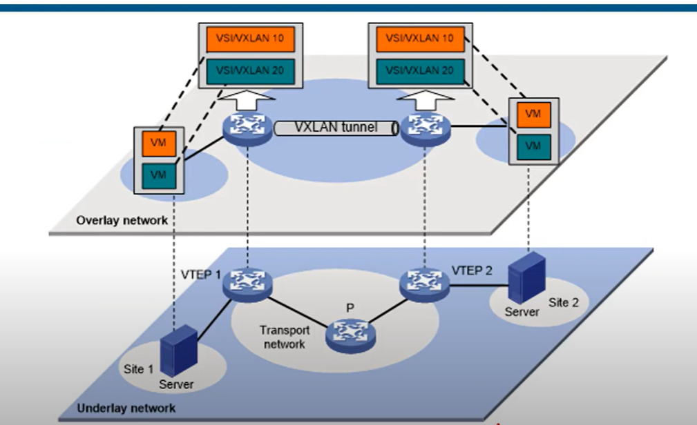
VXLAN
VXLAN stands for Virtual Extensible LAN**. It’s a networking technology used to create virtual Layer 2 networks (like VLANs) over a Layer 3 (IP) network, typically used in data centers and cloud environments**.
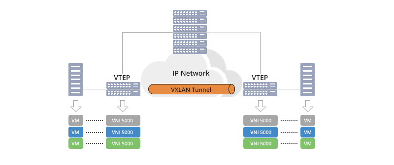
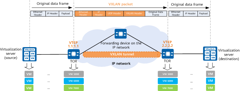
VXLAN is designed to deliver reliable and scalable data center networking services to managed service customers and is a technology for next-generation data center construction.
Cisco DNA Controller
- Cisco DNA Controller (Also called Cisco Digital Network Architecture) is a powerful SDN controller and management dashboard that allows you to take control of your network, optimize your network, and secure your remote workforce.
It is an appliance that provides a centralized graphical interface to design your network, add and configure devices, monitor your network and devices, and troubleshoot.
API
- API(Application Programming Interface): is a software intermediately that allows two applications to communicate with each other, APIs enable applications to exchange data and functionality easily and securely.
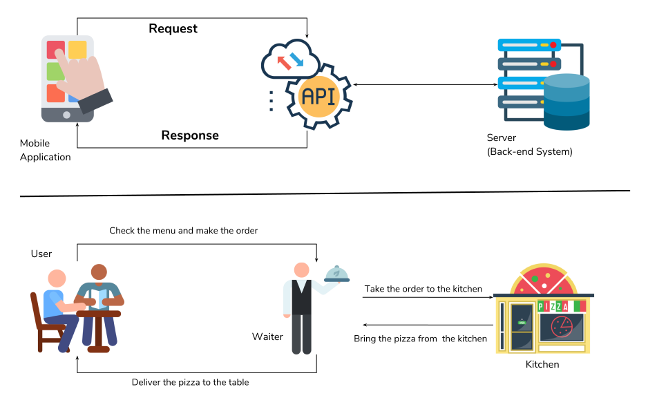
In SDN Architecture, APIs are used to communicate between apps and the SDN Controller(via The NBI), and between the SDN controller and the network devices (via the SBI).
The NBI typically uses REST APIs
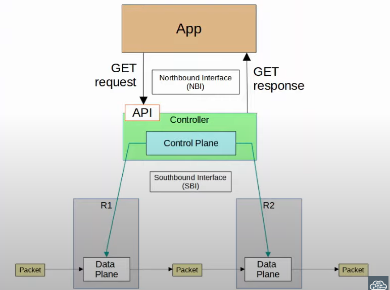
REST API
- A REST API (Representational State Transfer) or RESTful API) is a way applications communicate with each other using a set of rules.
- REST APIs use familiar commands like GET, POST, PUT, and DELETE. These commands are like asking the waiter to get (read), add (create), update, or delete information.
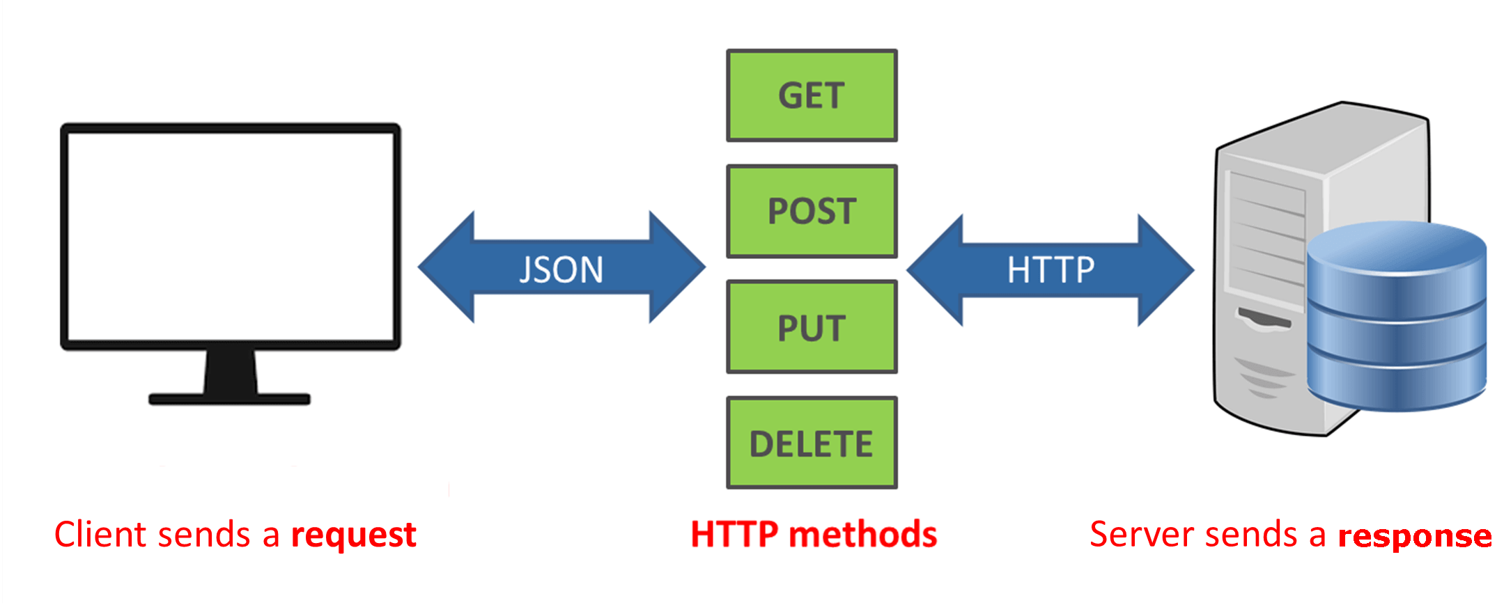
REST APIs communicate via HTTP requests to perform standard database functions like creating, reading, updating, and deleting records ( also known as CRUD) within resources.
CRUD and HTTP Methods
| HTTP method | CRUD | Example |
| GET | Read | 200(ok), what is the value of “ip_address” |
| POST | Create | 201(created), create variable “ip_address” and set the value to “192.168.3.1” |
| PUT/PATCH | update | 405(Method not allowed), unless you want to update every resource in the entire collection of resource. Example: change the value of “ip_address” to “192.168.0.2” |
| Delete | Delete | 405(Method not allowed), unless you want to delete the whole collection: delete “ip_address” |
Data Serialization
Serialization is the process of converting a data object—a combination of code and data represented within a region of data storage — into a series of bytes that saves the state of the object in an easily transmittable form.
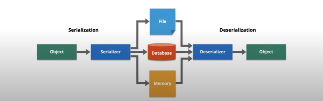
Data formats such as JSON and XML are often used for sorting serialized data.
- JSON(JavaScript Object Notation)
- XML(eXtensible Markup language)
YAML
JSON
JSON(JavaScript Object Notation) is a lightweight data interchange format. it is easy for humans to read and write.
The whitespace is insignificant.
JSON keys and Values
Key: a key is always string enclosed in quotation marks.
Value: A value can be a string, number, Boolean expression, array, or object.
Type of value:
Array: an associative array of values.
- Boolean: True or False.
- Number: An integer.
- Object: an associative value of key/value pairs.
String: a plain text character that usually forms a word.
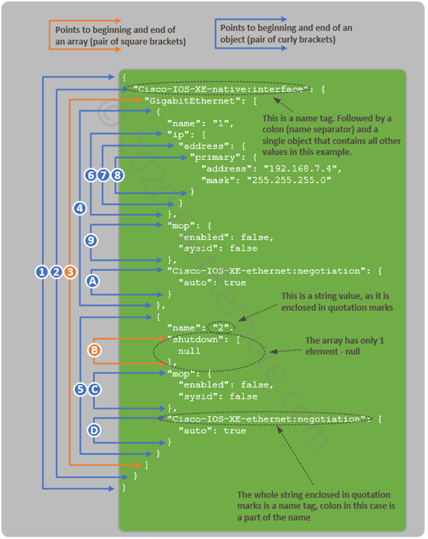
XML
- Extensible Markup Language (XML) is a tag-based language and if you know HTML, this will look familiar. each item you add has to start with .
The whitespace is insignificant.
YAML
YAML is a data serialization language that is often used for writing configuration files. YAML stands for yet another markup language, or YAML, not markup language, which emphasizes that YAML is for data, not documents.
whitespace is significant.
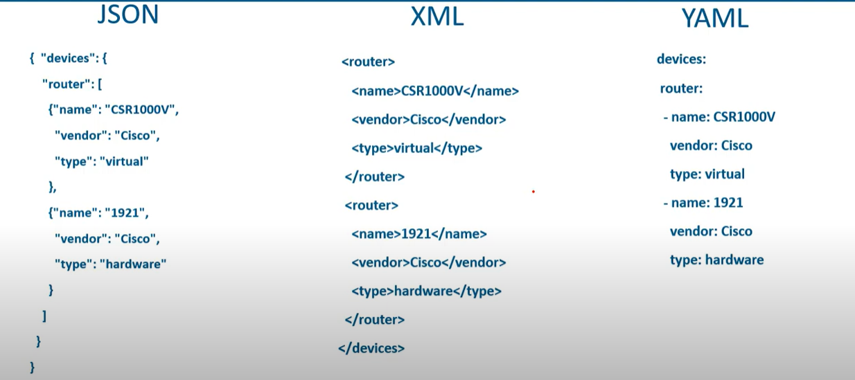
💡 JSON, with its compact syntax and wide-ranging support, has become the de facto standard for web applications and data interchange. Its simplicity ensures rapid parsing and broad compatibility across platforms
REST API Authentication
| Feature | Basic Auth | API Key | Access Token | OAuth 2.0 |
| Identifies User? | ✅ (username) | ❌ (app only) | ✅ (if user-scoped) | ✅ (via access token) |
| Authorization Level | Basic | App-level | Granular (scopes) | Granular (scopes) |
| Credential Rotation | Manual | Manual | Auto (refresh) | Auto (refresh) |
| Token Expiration | ❌ No | ❌ No | ✅ Yes | ✅ Yes |
| Security Best Practice | ❌ Weak | ⚠️ Medium | ✅ Strong | ✅✅ Strongest |
| Complexity | ✅ Simple | ✅ Simple | ⚠️ Medium | ❌ Complex |
| Ideal Use Case | Testing, Legacy | Internal APIs | User-access APIs | Web/Mobile login |
💡 REST-based authentication methods should always be used using HTTPS to prevent credentials from being intercepted.
How OAuth 2.0 Works
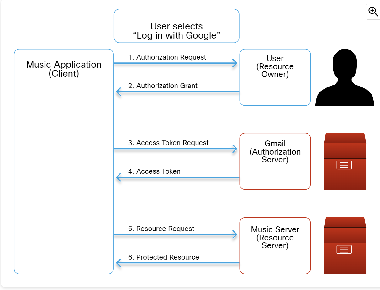
The details of the steps in the figure are as follows:
- Authorization Request:
- User clicks "Log in with Google" on the music platform.
- The music platform redirects the user to Google's login page, requesting access to their Gmail profile and email.
- Authorization Grant:
- User logs into Gmail and grants permission.
- Access Token Request:
- The music platform sends the authorization code and its own credentials to Google to request an access token.
- Access Token:
- Google verifies the code and the music platform's identity.
- Google issues an access token to the music platform.
- Resource Request:
- The music platform uses the access token to request the user's profile and email from Google.
Protected Resource:
- If the access token is valid, Google provides the requested information to the music platform.
Configuration Management
Configuration Management is the process of maintaining a computer system, server, and software in a desired, consistent state. It’s a way to make sure that a system performs as it’s expected as changes are made over time.
Infrastructure as Code (IaC) is the practice of provisioning and managing infrastructure (Server, networks, cloud resources) using a machine-readable configuration file (code) instead of manual configuration (e.g, CLI/GUI)
Configuration Management Tools
- Ansible
- CFEngine
- Puppet
- Chef
- Salt
Type of Configuration Management Tools
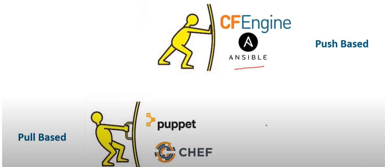
Push Base configuration management tools
Push configuration management tools initiate and push configuration changes from a central server or control node to the target system. The central server actively sends the updated configurations to the target systems.
- Centralized Control: A central server or control node is responsible for initiating and distributing configuration changes to the target systems.
- Immediate Updates: The target system receives and applies the configuration changes immediately from the configuration management server.
- Real-Time Interaction: Push-based configuration management typically involves real-time communication between the configuration server and the target systems.
- Agentless or Light Agents: push-based configuration management can be agentless, where the target systems fetch configuration changes using protocols like HTTP or SSH.
Pull Base configuration management tools
Pull-based configuration management tools enable target systems to independently fetch configuration from a central repository or server when needed. The target systems periodically or on demand request and retrieve the updated configurations.
- Decentralized Control: Configuration changes are stored in a central repository on the server, but the target systems independently retrieve changes when needed.
- Delay Updates: The target systems update their configuration only when they request and retrieve the updated configuration from the central server. Changes are not applied immediately upon availability.
- Scheduled or Triggered Retrieval: The target system can be configured to retrieve the configuration changes periodically, based on a schedule, or triggered by specific events or conditions.
- Agent-based Approach: Pull-based configuration management often relies on agents or client software installed on the target systems. These agents establish communication with the configuration management server and receive configuration updates.
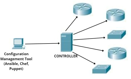
Ansible
- Ansible is an open-source community project sponsored by Red Hat.
- Ansible is the automation language that can be used across entire IT teams from systems and network administrators to developers and managers.
- It has only a master running on the server machine, but no agents running on the client machine. It uses an SSH connection to log in to client systems or nodes you want to configure.
- Ansible relies on modules and Python libraries to communicate with other devices.
- Modules can be written in different programming languages (mostly Python) to accomplish different tasks.
- Cisco devices can communicate with Ansible through SSH and SNMP.
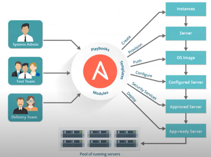
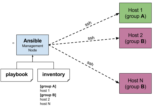
Playbooks are the files where Ansible code is written. Playbooks are written in YAML format. YAML stands for Yet Another Markup Language. Playbooks are one of the core features of Ansible and tell Ansible what to execute. They are like a to-do list for Ansible that contains a list of tasks.
“command_ios.yml” Playbook
---
- name: IOS Show Commands
hosts: "ios_devices"
gather_facts: false
connection: local
vars:
cli:
host: "{{ ansible_host }}"
username: "{{ username }}"
password: "{{ password }}"
transport: cli
tasks:
- name: ios show commands
ios_command:
commands:
- show version | i IOS
- show run | i hostname
provider: "{{ cli }}"
register: output
- name: show output of IOS
debug:
var: output
Inventory: The Ansible inventory file defines the hosts and groups of hosts upon which commands, modules, and tasks in a playbook operate.
“hosts” Inventory
[cisco_routers]
192.168.1.1 ansible_connection=network_cli ansible_network_os=ios ansible_user=your_username ansible_password=your_password ansible_become=yes ansible_become_method=enable ansible_become_password=your_enable_password
[cisco_switches]
192.168.2.5 ansible_connection=network_cli ansible_network_os=ios ansible_user=your_username ansible_password=your_password ansible_become=yes ansible_become_method=enable ansible_become_password=your_enable_password
💡 In a production environment, the best practice is to use a more secure method, such as Ansible Vault or Ansible Tower.
Terraform
Terraform is an open-source LaC tool developed by HashiCorp, designed to help professionals efficiently build, change, and version infrastructure safely and predictably.
Terraform uses providers, which are plugins that interact with devices through APIs like RESTCONF or NETCONF.
💡 RESTCONF and NETCONF are network configuration protocols that allow direct interaction with network devices. They provide standardized APIs for secure communication, used to modify device configurations and retrieve operational data.
- Like Ansible, it uses a push model and is agentless.
- A Terraform provider is essentially a plugin that allows Terraform to interact with different technologies. For example, Cisco offers several Terraform providers to configure devices.
- HCL is a configuration language designed to be both human-readable and machine-friendly, similar to JSON and XML.
- HCL is similar to JSON in data structure and uses braces for blocks and lists. However, HCL also includes features for configuration management, such as comments and a more flexible syntax.
Step 1: Create the Terraform configuration file.
# Assuming there is a provider that supports Cisco IOS XE RESTCONF
provider "cisco_ios_xe" {
host = "192.168.10.1"
username = "admin"
password = "adminpass"
secure = true # Assuming secure implies HTTPS/RESTCONF is being used securely
}
# Resource configuration for an interface
resource "cisco_ios_xe_interface" "gigabit1" {
name = "GigabitEthernet1"
description = "Uplink Interface"
enabled = true
}
# Output the operational status of the interface
output "interface_status" {
value = cisco_ios_xe_interface.gigabit1.operational_status
description = "Operational status of the GigabitEthernet1 interface."
}
Step 2. Use the Terraform Provider.
On the PC running Terraform, you need to install and configure the Cisco IOS XE Terraform Provider plugin. and enable RESTCONF or NETCONF on the target IOS XE device by entering the global configuration commands
Router1> enable
Router1# configure terminal
Router1(config)# restconf
Router1(config)# netconf-yang
Router1(config)# end
Router1# write memory
Step 3. Run Terraform Commands
admin@pc:~/terraform_project$ terraform init
admin@pc:~/terraform_project$ terraform plan
admin@pc:~/terraform_project$ terraform apply
- The terraform init command initializes the Terraform working directory.
- The terraform plan command creates an execution plan specifying what actions Terraform will take.
- The terraform apply command applies the changes required to reach the desired state of the configuration.
Puppet
Puppet is a configuration automation and deployment orchestration solution. It’s an open-source tool based on Ruby. For working, it is based on a Customized Domain Scripting Language (DLS) nearer to JSON. It runs as a master-client setup and uses a model-driven approach. Large enterprises use it widely to automate sysadmins who spend ages configuring, provisioning, troubleshooting, and maintaining server operations.

Chef
- Chef is an automation platform that provides an effective way to configure and manage infrastructure. Chef is based on Ruby and uses DL for writing the configurations. Its architecture is like the puppet master-agent model. It’s a pull-based configuration tool.
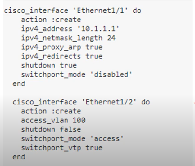
- Ansible: Known for its ease of use and agentless architecture, making it a good choice for beginners or smaller teams.
- Puppet: Excels in managing large-scale deployments and complex configurations, with a strong focus on security.
- Chef: Offers a high degree of flexibility and integrates well with infrastructure as code practices.
| Ansible | Puppet | Chef | |
| Key files defining actions | Playbook | Manifest | Recipe, Run-List |
| Communication Protocol | SSH | HTTPS(via REST API) | HTTPS (Via RESTAPI) |
| Key Port | 22 (SSH Port) | 8140 | 10002 |
| Agent/Agentless Based | Agentless | Agent-based(or agentless) | Agent-based |
| Push/Pull | Push | Pull | Pull |
| Architecture | Only Master | master-agent | master-agent |
Artificial Intelligence and Machine Learning
Artificial Intelligence (AI) can be explained as the simulation of human intelligence by computer systems. This includes understanding language, recognizing patterns, solving complex problems, and learning from experience. These processes include learning, reasoning, and self-correction.
Machine Learning (ML) is a subset of AI. ML enables machines to mimic intelligent human behavior by learning from data without being explicitly programmed.
Narrow AI focuses on executing particular tasks with high proficiency, such as Google Translate
This service uses Neural Machine Translation (NMT) to convert text or speech from one language to another. It improves over time by processing vast amounts of bilingual data.
Generative AI refers to artificial intelligence systems that create new content, such as text, images, music, or code, based on patterns and knowledge learned from large datasets.
Discriminative AI focuses on classifying or predicting by learning the differences between classes, not how the data is generated.

Descriptive AI analyzes data to describe what is happening or has happened. It focuses on understanding past and present data to provide insights and a clear picture of current or historical events, such as Tableau, Google Analytics.
Predictive AI refers to artificial intelligence systems designed to make predictions about future events or outcomes based on historical data.
Predictive AI is widely used in various fields, such as finance for stock market forecasting, healthcare for predicting patient outcomes, and marketing for customer behavior prediction
How AI Learns
- Supervised Learning is a machine learning technique where an algorithm learns from a labeled dataset to make predictions or decisions.
In network security, supervised machine learning is utilized to categorize network traffic or predict security threats by training AI systems with datasets that have already been tagged with outcomes, such as "safe" or "malicious" traffic, as shown in the figure.
- Unsupervised Learning does not rely on pre-labeled data. In situations where there are vast amounts of data, unsupervised learning can be used to find potentially useful insights.

For example, video services such as Netflix capture the video habits of their large customer base. Using this information and these algorithms, it can identify customers with similar viewing habits and recommend specific movies for them to watch.
- Reinforcement Learning is a type of machine learning where an agent learns to make decisions by performing actions in an environment and receiving rewards or penalties based on the outcomes. The goal is to maximize cumulative rewards over time.
AlphaZero used reinforcement learning to teach itself chess. It played many games against itself, starting with random moves and gradually improving its strategies. AlphaZero used a reward function that gave positive values for winning and negative values for losing, which encouraged it to find better strategies for success.
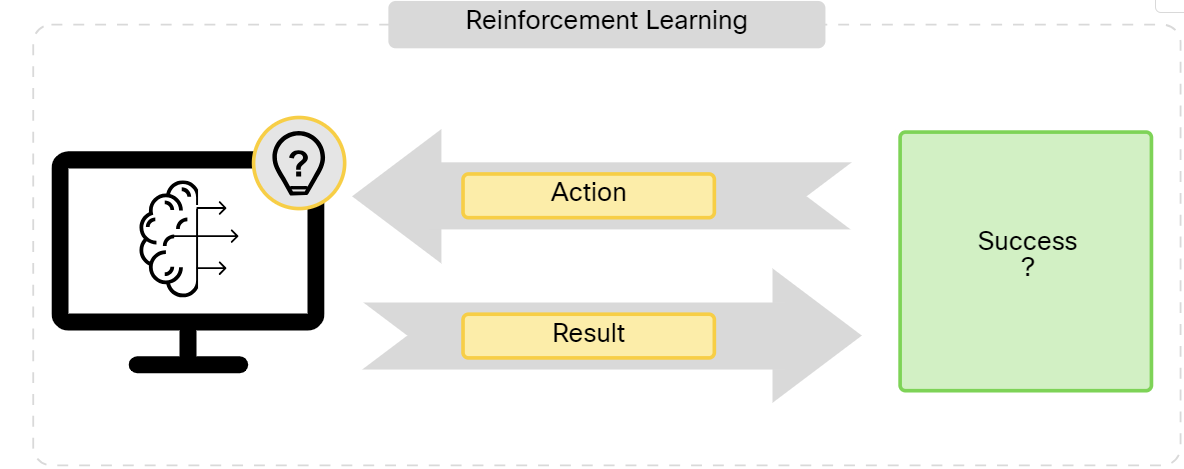
Hallucination and RAG
AI systems learn from vast amounts of data to make predictions and generate content, but they are not perfect. For example, even if you provide detailed and accurate prompts to a generative AI model like ChatGPT, it can still produce incorrect or misleading information. This issue is known as hallucination.
Retrieval-Augmented Generation (RAG) is a technique that helps reduce hallucination and outdated answers in LLMs. RAG combines a retrieval system with a generative model. When given a prompt, the retrieval system first fetches relevant documents or information from a large database or knowledge source. Then, the generative model uses this information to generate a response
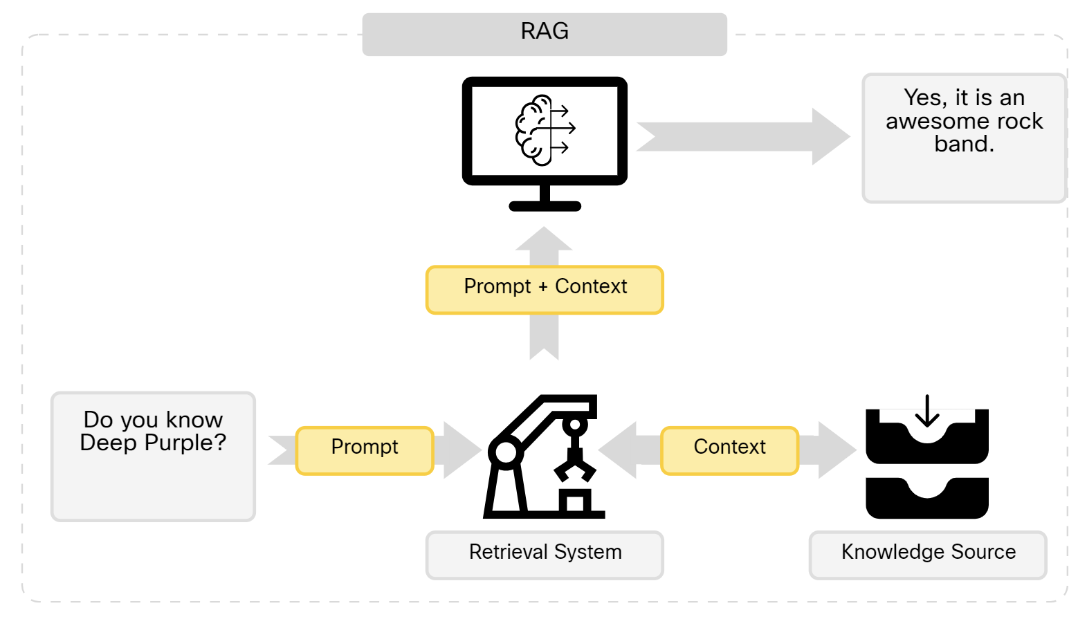
You can use your own RAG system with ChatGPT by uploading a PDF document and directing ChatGPT to consult it when responding. For example, if you upload the PDF manual of the Cisco OSPF Configuration Guide, you can query ChatGPT for step-by-step instructions, such as: “How do I configure OSPF directly on the interfaces?” In this way, you make sure that it’s using the PDF instead of its training data to answer your questions.
From SDN to IBN and AI
Intent-Based Networking (IBN) is a modern approach to network management that uses automation and artificial intelligence to bridge the gap between what a network needs to do (intent) and how it is actually configured and operating. It's designed to make networks more agile, secure, and easier to manage at scale.
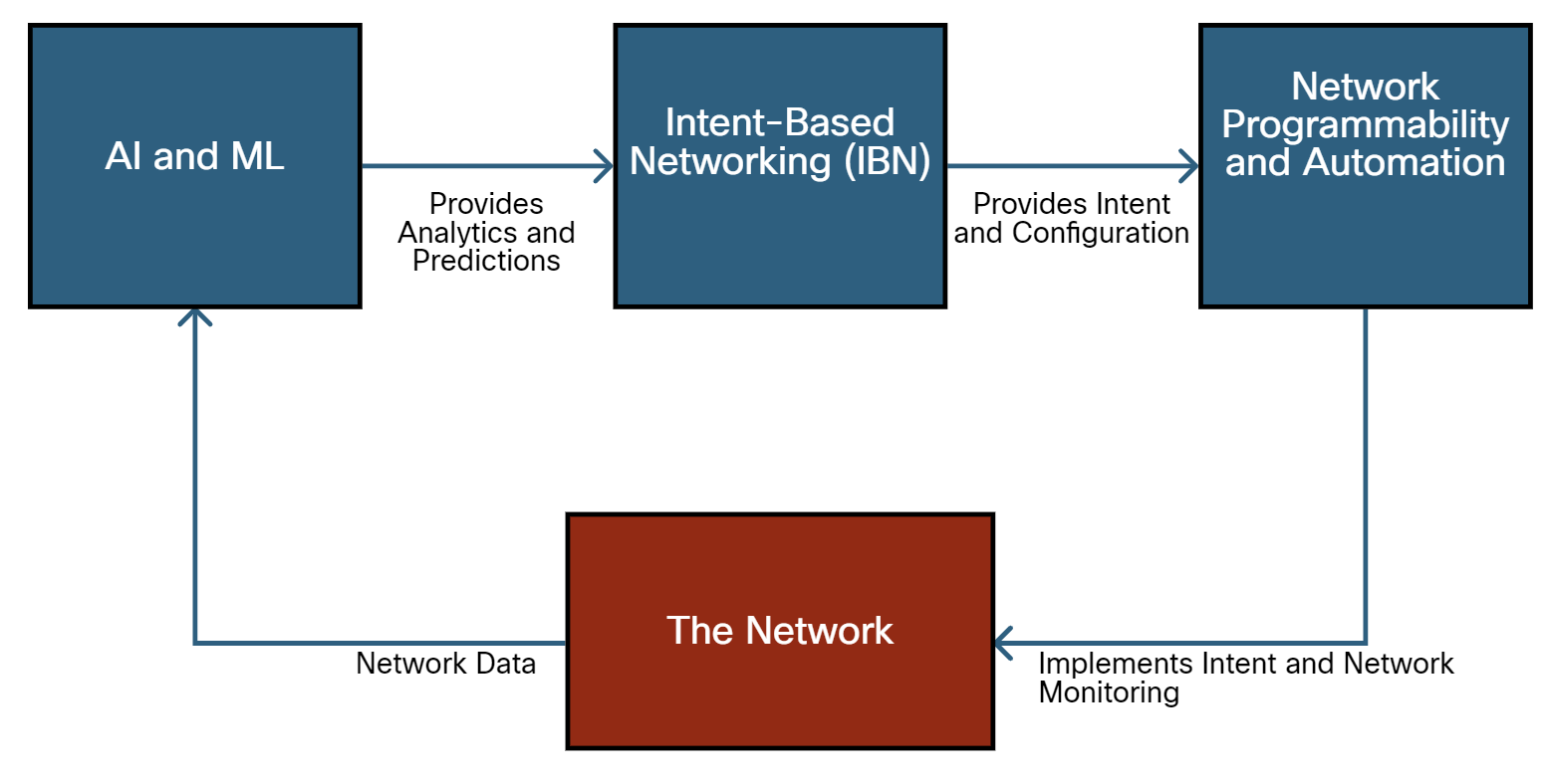
In a network with AI and IBN enabled, it begins with AI and ML, which provide analytics and predictions to the Intent-Based Networking (IBN) system. This IBN system then offers intent and configuration to the Network Programmability and Automation component, which implements intent and network monitoring in The Network. The network sends data back to the AI and ML system to conduct further analysis and predictions.
What can IBN and AI solve?
- High Latency: Due to inefficient routing and traffic congestion.
- Security Vulnerabilities: Inconsistent firewall configurations across different network segments.
- Manual Configuration Errors: Leading to Network Downtime and Performance Issues.
- Scalability Challenges: Difficulty in scaling the network to accommodate new devices and users.
Two types of AI systems
Black Box AI models operate without showing their internal workings or logic to the user. AlphaZero is an example of this; it makes decisions that are not clear to the user.
Explainable AI (XAI) aims to make AI processes and decisions clear and understandable to humans. It ensures transparency and trust in AI decisions, allowing professionals to understand and validate the AI's reasoning.
Example: XAI enables network administrators to comprehend AI-driven decisions regarding network configurations, security measures, and optimizations, ensuring that network management is transparent and trustworthy.
AI in Network Optimization
AI is revolutionizing network optimization by enhancing traffic analysis, reliability, and resource utilization. It analyzes traffic patterns to predict congestion, routes data to minimize latency, and identifies potential failures to ensure continuous service. This dynamic adaptation ensures optimal performance in modern digital communications.
AI in Network Security
AI plays a crucial role in network security by using advanced machine learning models to protect against cyber threats. By learning from network data and user behavior, AI can identify potential security incidents, providing a dynamic defense that adapts to evolving threats.
Additional Info
What is the iDRAC Port?
The iDRAC Port is a network port on Dell servers that allows for remote management and server monitoring through the Integrated Dell Remote Access Controller (iDRAC). iDRAC is a powerful tool that provides IT administrators access to system diagnostics, hardware components, system logs, and BIOS settings. The iDRAC Port provides a separate IP address that connects to the iDRAC, allowing administrators to manage the server regardless of its power state remotely.
Single Point of Failure
A singe point of failure is a point where the entire system can crash in case that point crashes.
- For example, if we have only one database in a system and it crashes then our whole system will stop functioning. even if other services are working, it won’t matter.
Identifying a Single Point of Failure in a system
IF we have all the components connected to a single component then the single component will become a single point of failure.
Avoiding Single Point of Failure
- Adding more nodes
If the gateway service is a single point of failure then we can add another node. If the first one crashes we can use the second one. Or we can distribute load across both the nodes.
- Adding Load Balancers
When we are using multiple nodes for a service we also need to distribute load across the nodes. For that, we use the load balancer. Since a single load balancer is a Single Point of Failure, we will use multiple load balancers.
https://www.youtube.com/watch?v=wwwAXlE4OtU
https://medium.com/@interviewready/single-point-of-failure-591f853ee5aa
https://www.youtube.com/watch?app=desktop&v=ZmLxb8HzQX4
Peer-to-Peer Applications
A P2P application allows a device to act as both a client and a server within the same communication, as shown in the figure. In this model, every client is a server and every server is a client. P2P applications require that each end device provide a user interface and run a background service.
Some P2P applications use a hybrid system where resource sharing is decentralized, but the indexes that point to resource locations are stored in a centralized directory. In a hybrid system, each peer accesses an index server to get the location of a resource stored on another peer.
Cellular internet access uses a cell phone network to connect. Wherever you can get a cellular signal, you can get cellular internet access. Performance will be limited by the capabilities of the phone and the cell tower to which it is connected. The availability of cellular internet access is a real benefit for people in areas that would otherwise have no internet connectivity at all, or for people who are constantly on the move. The downside of cellular connectivity is that the carrier usually meters the bandwidth usage of the connection and may charge extra for bandwidth that exceeds the contract data plan.
Switch configuration for First Time
- Step 1: Plug in and power on the switch (ensure it is fully booted).
- Step 2: Connect Ethernet cables from network devices (e.g., computers, routers, IP phones) to the switch ports.
- Step 3: Check the link lights to confirm that the connections are active and the devices are recognized by the switch.